Communication Processor Module
MOTOROLA
MPC823e REFERENCE MANUAL
16-85
SDMA
COMMUNICATION
16
PROCESSOR MODULE
16.5.2 The SDMA Registers
The SDMA channels share a configuration register, address register, and status register.
They are all controlled by the configuration of the serial communication controllers, serial
management controllers, serial peripheral interface, and I
2
C controller.
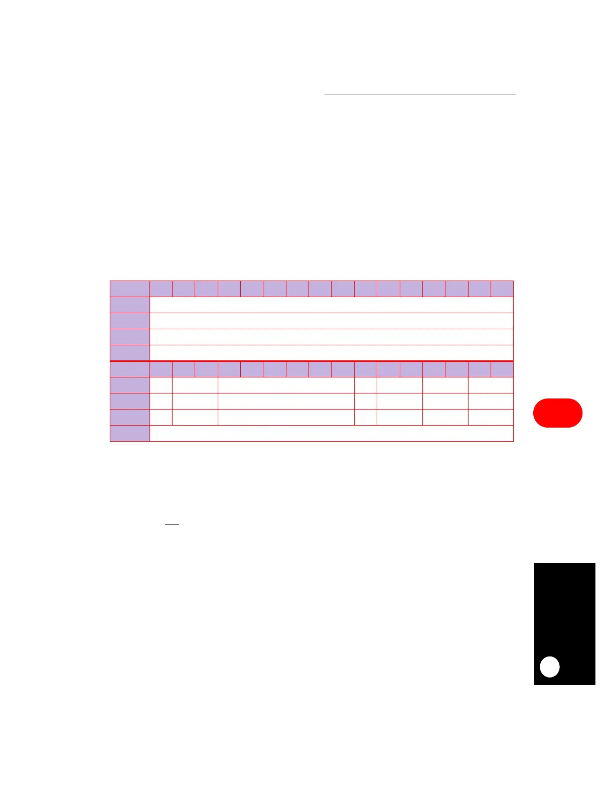
16.5.2.1 SDMA CONFIGURATION REGISTER.
The 32-bit SDMA configuration register
(SDCR) is used to configure all 16 SDMA channels. It is always read/write in supervisor
mode, even though writing to the SDCR is not recommended unless the communication
processor module is disabled. The control provided by this register has interactions with the
DMA controllers in the LCD and video controller modules of the MPC823e. Refer to
Section 18.3.6 DMA Control
and
Section 18.3.1 FIFO Control
for more information
regarding those modules.
Bits 0–16—Reserved
These bits are reserved and must be set to 0.
FRZ—Freeze
This field determines the action to be taken when the FRZ signal is asserted. The SDMA
negates the BR
signal and keeps it that way until FRZ is negated or a reset occurs.
00 = The SDMA channels ignore the FRZ signal.
01 = Reserved.
10 = The SDMA channels freeze on the next bus cycle.
11 = Reserved.
SDCR
BIT
0 1 2 3 4 5 6 7 8 9 10 11 12 13 14 15
FIELD
RESERVED
RESET
0
R/W
R
ADDR
(IMMR & 0xFFFF0000) + 0x030
BIT
16 17 18 19 20 21 22 23 24 25 26 27 28 29 30 31
FIELD
RES FRZ RESERVED LAM RESERVED LAID RAID
RESET
00 0 0000
R/W
R R R R/W R R R
ADDR
(IMMR & 0xFFFF0000) + 0x030