Communication Processor Module
MOTOROLA MPC823e REFERENCE MANUAL 16-117
SERIAL
I/F
COMMUNICATION
16
PROCESSOR MODULE
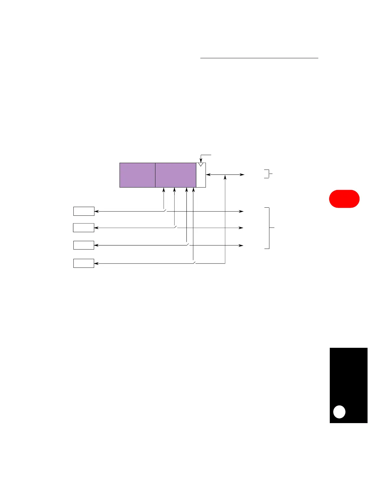
16.7.3 Enabling Connections to the Time-Slot Assigner
Each serial communication controller and serial management controller can be
independently enabled to connect to the time-slot assigner. A serial communication
controller is connected to the time-slot assigner by setting the SCx bit in the SICR. The serial
management controllers are connected to the time-slot assigner by setting the SMCx field
of the SIMODE register. Additionally, the TDMA interface must be enabled before it can be
connected to the time-slot assigner by setting the ENx field in the SIGMR. Once there is a
connection, the exact routing decisions are made in the serial interface RAM. Refer to
Figure 16-45 for more information.
16.7.4 Serial Interface RAM Operation
The serial interface has two 64 × 32-bit static RAMs that are used to control the routing of
the TDMA channel to the serial communication and management controllers. These RAMs
are uninitialized after power-on and, to avoid unwanted results, the host CPU must program
them before enabling the multiplexed channels. The RAMs consist of 16-bit entries that
define the routing control and each entry can control anywhere from 1 to 16 bits or 1 to 16
bytes. In addition to the routing, up to four strobe pins (all active high) can be asserted,
depending on how the RAM is programmed. You can configure the serial interface RAM in
the following formats to support the TDM channels:
• One multiplexed channel with static frames
• One multiplexed channel with dynamic frames
• Two multiplexed channels with static frames
• Two multiplexed channels with dynamic frames
Figure 16-45. Enabling Connections Through the Serial Interface
TDM PINS
TIME-SLOT
ASSIGNER
CONTROL LOGIC
EN
ENA=1 TO ENABLE
SCC2
SCC2 PINS
SC2=1
SMC1 SMC1 PINS
SMC1=1
SMC2
SMC2=1
SC2=0
SMC1=0
SMC2=0
MULTIPLEXED
INTERFACE
NONMULTIPLEXED
INTERFACE
SERIAL
INTERFACE
RAM
SCC3
SCC3 PINS
SC3=0
SC3=1