Communication Processor Module
16-160 MPC823e REFERENCE MANUAL MOTOROLA
BRGs
COMMUNICATION
16
PROCESSOR MODULE
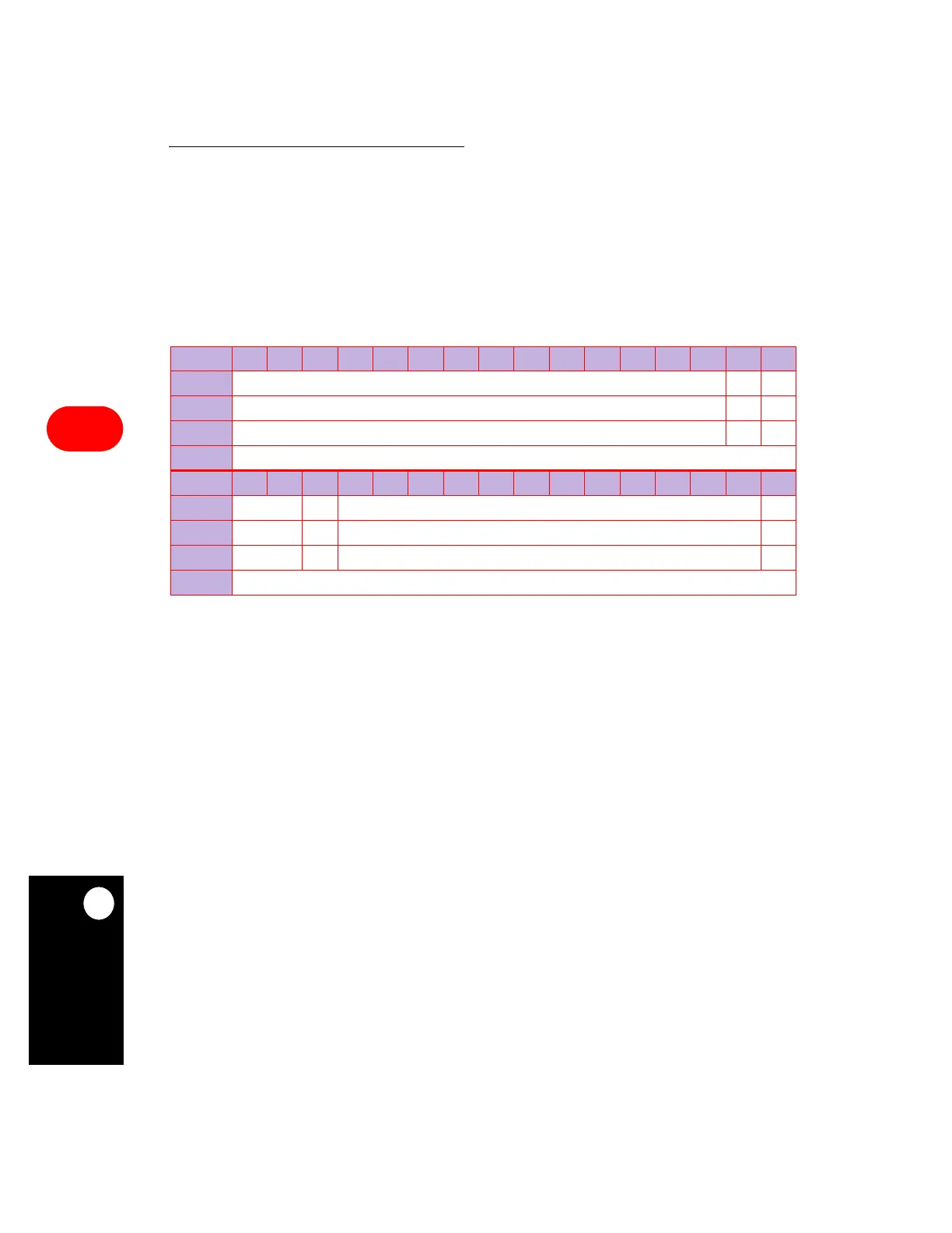
16.8.2 Baud Rate Generator Configuration Registers
The 32-bit, memory-mapped baud rate generator configuration (BRGC1–4) registers are
used to configure the baud rate generators. At reset, the baud rate generators are disabled
and the BRGOx output clock is high. These registers can be written at any time and you do
not need to disable any internal or external devices connected to the BRGOx output clock.
Changes to the baud rate generators occur at the end of the next BRG clock cycle (no spikes
occur on the BRGOx output clock).
Bits 0–13—Reserved
These bits are reserved and must be set to 0.
RST—Reset Baud Rate Generator
This bit performs a software reset of the baud rate generator identical to that of an external
reset. A reset disables the baud rate generator and sets the BRGOx output clock. This can
only be seen externally if the BRGOx function is enabled to reach the corresponding port A
or B parallel I/O pin.
0 = Enable the baud rate generator.
1 = Reset the baud rate generator (software reset).
EN—Enable Baud Rate Generator Count
This bit is used to dynamically stop the baud rate generator from counting, which may be
useful for low-power modes.
0 = Stop all clocks to the baud rate generator.
1 = Enable clocks to the baud rate generator.
BRGC1–BRGC4
BIT 0 1 2 3 4 5 6 7 8 9 10 11 12 13 14 15
FIELD
RESERVED RST EN
RESET
000
R/W
R/W R/W R/W
ADDR
(IMMR & 0xFFFF0000) + 0x9F0 (BRGC1), 0x9F4 (BRGC2), 0x9F8 (BRGC3), 0x9FC (BRGC4)
BIT 16 17 18 19 20 21 22 23 24 25 26 27 28 29 30 31
FIELD
EXTC ATB CD DIV16
RESET
0000
R/W
R/W R/W R/W R/W
ADDR
(IMMR & 0xFFFF0000) + 0x9F2 (BRGC1), 0x9F6 (BRGC2), 0x9FA (BRGC3), 0x9FE (BRGC4)