Communication Processor Module
16-170
MPC823e REFERENCE MANUAL
MOTOROLA
SCCs
COMMUNICATION
16
PROCESSOR MODULE
SYNL—Sync Length (Transparent Mode Only)
This field determines the operation of the SCCx receiver that is configured for totally
transparent operation.
00 = The sync pattern in the DSR (described in
Section 16.9.4 Data Synchronization
Register
) is not used. An external sync signal is used instead.
01 = 4-bit sync. The receiver synchronizes on a 4-bit sync pattern stored in the DSR.
This character and additional syncs can be programmed to be stripped using the
Sync character in the parameter RAM. The transmitter transmits the entire
contents of the DSR prior to each frame.
10 = 8-bit sync. The receiver synchronizes on an 8-bit sync pattern stored in the DSR.
The transmitter transmits the entire contents of the DSR prior to each frame.
11 = 16-bit sync. The receiver synchronizes on a 16-bit sync pattern stored in the DSR.
The transmitter transmits the DSR prior to each frame.
RTSM—RTS Mode
This bit indicates the mode of the request-to-send modem signal. It can be changed on-the-
fly.
0 = Send idles between frames as defined by the protocol and the TEND bit in the
GSMR_L. RTSx
is negated between frames (default).
1 = Send flags/syncs between frames according to the protocol. RTSx
is always
asserted when a serial communication controller is enabled.
RSYN—Receive Synchronization Timing (Transparent Mode Only)
0 = Normal operation.
1 = If the CDS bit is set to 1, then the CDx
signal must be asserted on the second bit
of the receive frame, rather than the first.
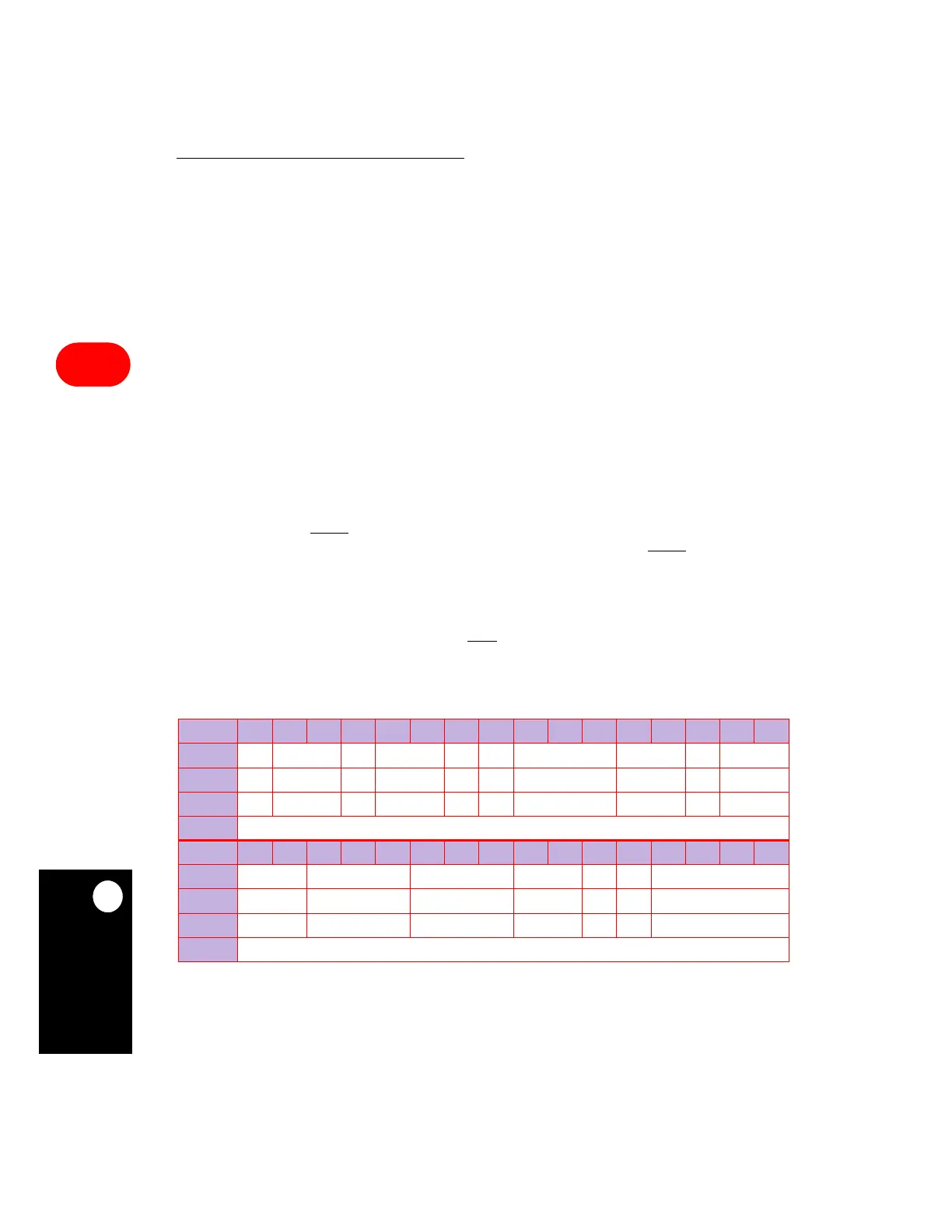
GSMR_L
BIT
0 1 2 3 4 5 6 7 8 9 10 11 12 13 14 15
FIELD
RES EDGE TCI TSNC RINV TINV TPL TPP TEND TDCR
RESET
000000 0 000
R/W
R/W R/W R/W R/W R/W R/W R/W R/W R/W R/W
ADDR
(IMMR & 0xFFF0000) + 0xA20
BIT
16 17 18 19 20 21 22 23 24 25 26 27 28 29 30 31
FIELD
RDCR RENC TENC DIAG ENR ENT MODE
RESET
00 00000
R/W
R/W R/W R/W R/W R/W R/W R/W
ADDR
(IMMR & 0xFFF0000) + 0xA22