Communication Processor Module
MOTOROLA MPC823e REFERENCE MANUAL 16-227
COMMUNICATION
16
SCCs
16.9.15.18 SCCx UART EVENT REGISTER.When a serial communication controller is in
UART mode, the 16-bit memory-mapped SCCx event register is referred to as the SCCx
UART event register (SCCE–UART). Since each protocol has specific requirements, the
SCCE bits are different for each implementation. This register is used to report events
recognized by the UART channel and to generate interrupts. When an event is recognized,
the SCCx UART controller sets the corresponding bit in the UART event register. Interrupts
generated by this register can be masked in the SCCM–UART register. An example of
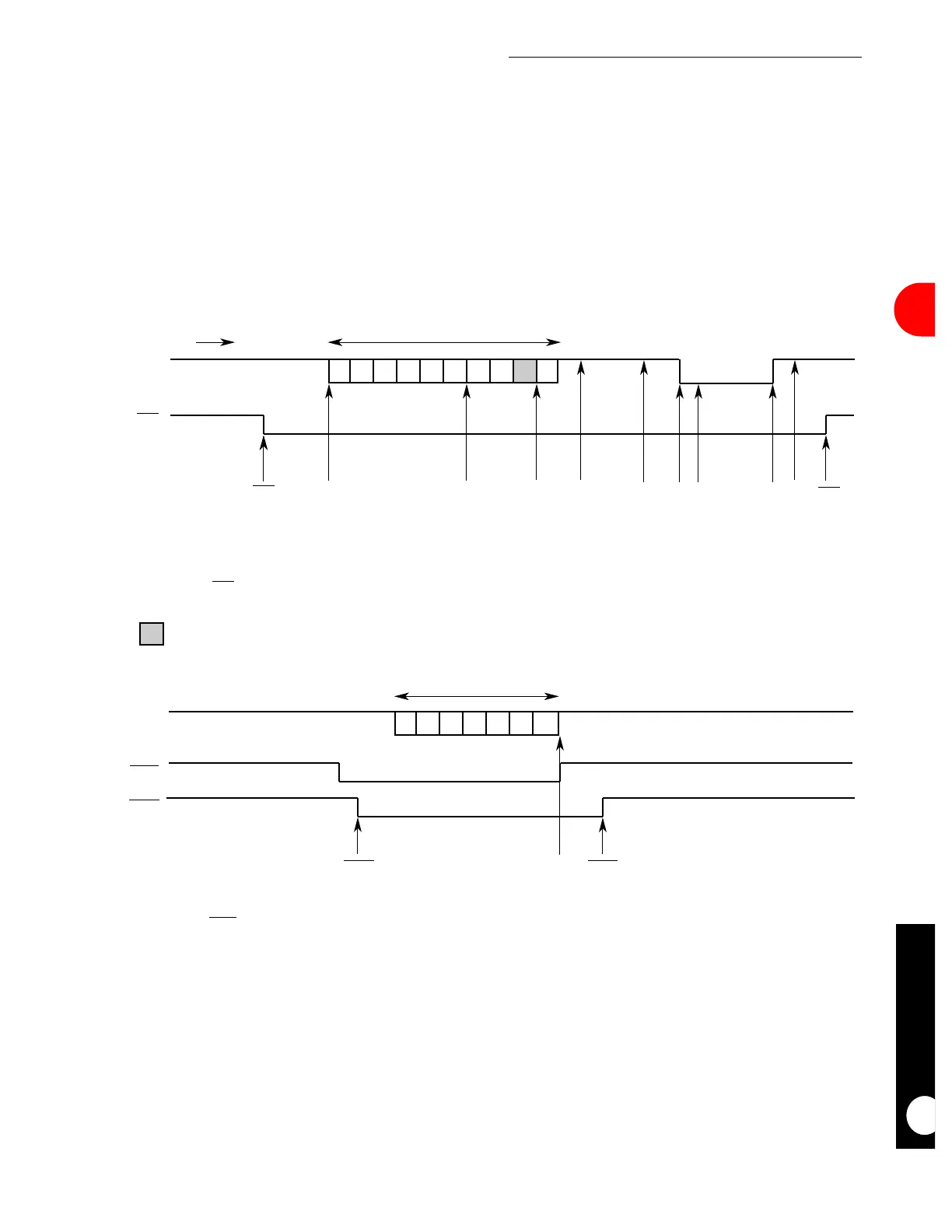
interrupts that can be generated by the SCCx UART controller is illustrated in Figure 16-77.
Figure 16-77. SCCx UART Interrupt Event Example
LINE IDLE
10 CHARACTERS
CHARACTERS
RECEIVED BY UART
TIME
RXDx
CDx
LINE IDLE
LINE IDLE
7 CHARACTERS
CTSx
LINE IDLE
TXDx
RTSx
IDL RX
CDx
CDxRX CCR
CTSx
CTSx
TX
BREAK
BRKs
NOTES:
1. The first receive event assumes receive buffers are 6 bytes each.
2. The second IDL event occurs after an all-ones character is received.
3. The second RX event position is programmable based on the MAX_IDL value.
4. The BRKs event occurs after the first break character is received.
5. The CDx event must be programmed in the port C parallel I/O, not in the SCC itself.
NOTES:
1. TX event assumes all seven characters were put into a single buffer and CR is set to 1 in the TX buffer descriptor.
2. The CTSx event must be programmed in the port C parallel I/O, not in the SCC itself.
UART SCCE
EVENTS
UART SCCE
EVENTS
CHARACTERS
TRANSMITTED BY UART
IDL
A receive control character defined not to be stored in the receive buffer.
LEGEND:
IDL IDLBRKe