Communication Processor Module
16-234 MPC823e REFERENCE MANUAL MOTOROLA
COMMUNICATION
16
SCCs
16.9.16.1 FEATURES.The following list summarizes the main features of the SCCx in
HDLC mode:
• Flexible data buffers with multiple buffers per frame
• Separate interrupts for frames and buffers (receive and transmit)
• Received frames threshold to reduce interrupt overhead
• Can be used with the SCCx DPLL
• Four address comparison registers with mask
• Maintenance of five 16-bit error counters
• Flag/abort/idle generation or detection
• Zero insertion/deletion
• 16- or 32-bit CRC-CCITT generation/checking
• Detection of nonoctet aligned frames
• Detection of frames that are too long
• Programmable flags (0–15) between successive frames
• Automatic retransmission in case of collision
16.9.16.2 SCCx HDLC CHANNEL FRAME TRANSMISSION PROCESS.The HDLC
transmitter is designed to operate with little or no intervention from the core. When the core
enables one of the transmitters, it starts transmitting flags or idles as programmed in the
PSMR–SCC HDLC register. The SCCx HDLC controller polls the first buffer descriptor in the
transmit channel buffer descriptor table. When there is a frame to transmit, the SCCx HDLC
controller fetches the data from memory and starts transmitting the frame after it transmits
the minimum number of flags that you specify between frames. When the end of the current
buffer descriptor has been reached and the last buffer in the frame bit is set, the CRC and
closing flag are appended. In HDLC mode, the least-significant bit of each octet and the
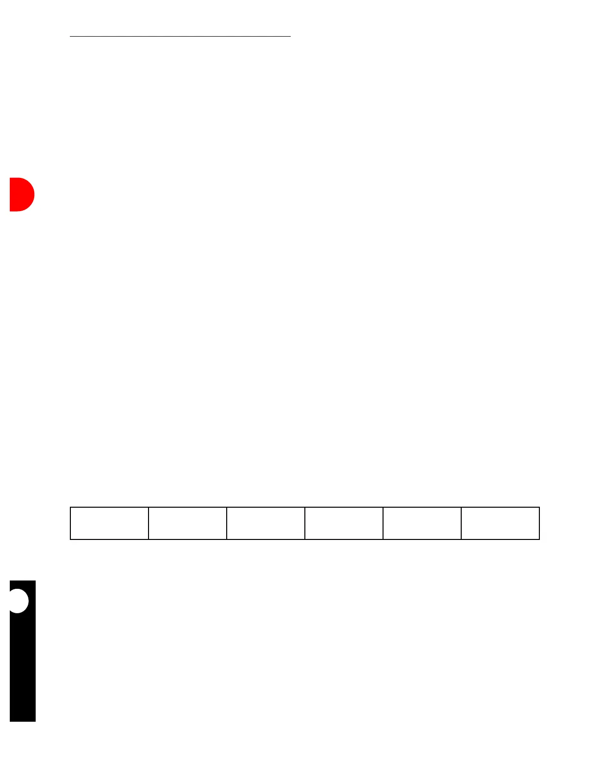
most-significant bit of the CRC are transmitted first. An HDLC frame is illustrated in
Figure 16-78.
After a closing flag is transmitted, the SCCx HDLC controller writes the frame status bits into
the buffer descriptor and clears the R bit. When you reach the end of the current buffer
descriptor and the last bit is not set, only the R bit is cleared. In either mode, an interrupt can
be issued if the I bit in the TX buffer descriptor is set. The SCCx HDLC controller then
proceeds to the next TX buffer descriptor in the table. This method allows you to be
interrupted after each buffer, a specific buffer, or each frame.
OPENING FLAG ADDRESS CONTROL
INFORMATION
(OPTIONAL)
CRC CLOSING FLAG
8 BITS 16 BITS 8 BITS 8N BITS 16 BITS 8 BITS
Figure 16-78. SCCx HDLC Framing Structure