Communication Processor Module
16-242 MPC823e REFERENCE MANUAL MOTOROLA
COMMUNICATION
16
SCCs
• CRC—When this error occurs, the channel writes the received CRC to the data buffer,
closes the buffer, sets the CR bit in the RX buffer descriptor, and generates the RXF
interrupt if it is enabled. The channel also increments the CRC error counter. After
receiving a frame with a CRC error, the receiver enters hunt mode. An immediate back-
to-back frame is still received. CRC checking cannot be disabled, but the CRC error can
be ignored if checking is not required.
16.9.16.8 SCCx HDLC MODE REGISTER.When a serial communication controller is in
HDLC mode, the 16-bit, memory-mapped, read/write protocol-specific mode register is
referred to as the SCCx HDLC mode register (PSMR–SCC HDLC). Since each protocol has
specific requirements, the PSMR bits are different for each implementation.
NOF—Number of Flags
This field signifies the minimum number of flags between or before frames. If NOF = 0000,
then no flags are inserted between the frames. Thus, the closing flag of one frame is
immediately followed by the opening flag of the next frame in the case of back-to-back
frames. These bits can be modified on-the-fly.
CRC—CRC Selection
00 = 16-bit CCITT-CRC (HDLC). X16 + X12 + X5 + 1.
01 = Reserved.
10 = 32-bit CCITT-CRC (Ethernet and HDLC). X32 + X26 + X23 + X22 + X16 + X12 +
X11 + X10 + X8 + X7 + X5 + X4 + X2 + X1 +1.
11 = Reserved.
RTE—Retransmit Enable
0 = No retransmission.
1 = Automatic frame retransmission is enabled. Retransmission only occurs if the lost
CTSx
occurs on the first or second buffer of the frame.
Bits 7 and 13–15—Reserved
These bits are reserved and must be set to 0.
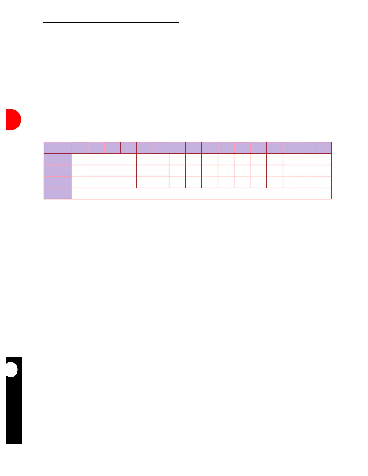
PSMR–SCC HDLC
BIT 0 1 2 3 4 5 6 7 8 9 10 11 12 13 14 15
FIELD NOF CRC RTE RES FSE DRT BUS BRM MFF RESERVED
RESET 0 0 0000000 0
R/W R/W R/W R/W R/W R/W R/W R/W R/W R/W R/W
ADDR (IMMR & 0xFFFF0000) + 0xA28