Communication Processor Module
16-274
MPC823e REFERENCE MANUAL
MOTOROLA
COMMUNICATION
16
SCCs
16.9.19.8 SCCx ASYNC HDLC PARAMETER RAM MEMORY MAP.
When configured as
an SCCx ASYNC HDLC controller, a serial communication controller overlays the structure
used in Table 16-24 with the SCCx ASYNC HDLC parameters described in Table 16-28.
• C_MASK—This value must be initialized with 0x0000F0B8.
• C_PRES—This value must be initialized with 0x0000FFFF.
• BOF—This value must be initialized to the beginning of the flag character (PPP is 0x7E
and IRLAP is 0xC0).
• EOF—This value must be initialized to the end of the flag character (PPP is 0x7E and
IrLAP is 0xC1).
• ESC—This value must be initialized to the control escape character (PPP is 0x 7D and
IrLAP is 0x7D).
• Reserved—These areas are temporary storage locations for the microcode. They must
not be initialized or modified.
• ZERO—You must set this field to zero.
• RFTHR—The received frames threshold indicates how many frames are received
before the RXF bit is set in the SCCE–ASYNC HDLC register.
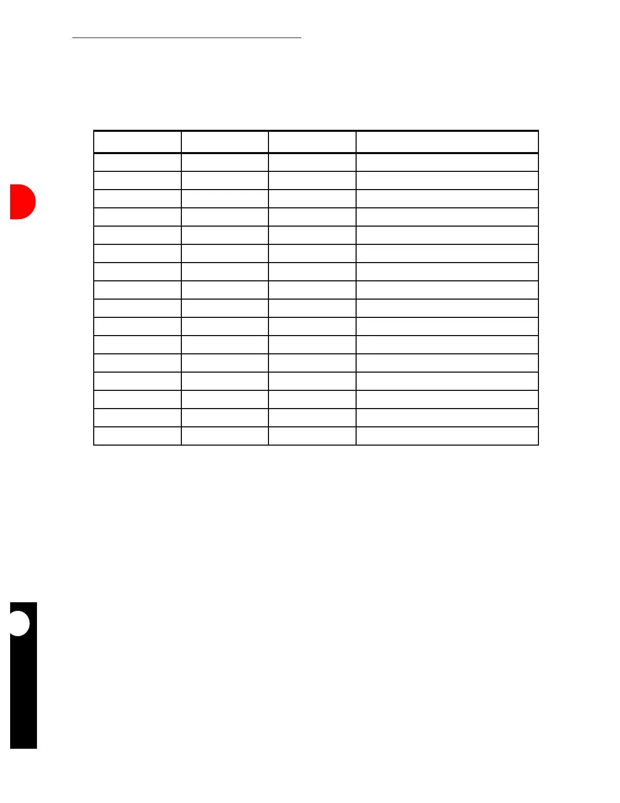
Table 16-28. SCCx ASYNC HDLC Parameter RAM Memory Map
ADDRESS NAME WIDTH DESCRIPTION
SCCx Base+34 C_MASK Word CRC Constant
SCCx Base+38 C_PRES Word CRC Preset
SCCx Base+3C BOF Half-word Beginning Of Flag Character
SCCx Base+3E EOF Half-word End Of Flag Character
SCCx Base+40 ESC Half-word Control Escape Character
SCCx Base+42 RES Half-word Reserved
SCCx Base+44 RES Half-word Reserved
SCCx Base+46 ZERO Half-word Reserved
SCCx Base+48 RES Half-word Reserved
SCCx Base+4A RFTHR Half-word Received Frames Threshold
SCCx Base+4C RES Half-word Reserved
SCCx Base+4E RES Half-word Reserved
SCCx Base+50 TXCTL_TBL Word TX Control Character Mapping Table
SCCx Base+54 RXCTL_TBL Word RX Control Character Mapping Table
SCCx Base+58 NOF Half-word Number of Opening Flags
SCCx Base+5A RES Half-word Reserved
NOTE: You are only responsible for initializing the items in bold.
SCCx Base = (IMMR & 0xFFFF0000) + 0x3D00 (SCC2 ) and 0x3E00 (SCC3).