Communication Processor Module
16-280 MPC823e REFERENCE MANUAL MOTOROLA
COMMUNICATION
16
SCCs
16.9.19.12.2 SCCx ASYNC HDLC Receive Buffer Descriptor. The SCCx ASYNC HDLC
controller uses the receive (RX) buffer descriptor to report information about each buffer’s
received data. An example of the RX buffer descriptor process is illustrated in Figure 16-80.
The first word of the RX buffer descriptor contains control and status bits. Bit 0 is set by the
core when the buffer is available to the SCCx ASYNC HDLC controller and it is cleared by
the controller when the buffer is full.
E—Empty
0 = The data buffer associated with this buffer descriptor is filled with data or stops
receiving because an error condition occurred. The core is free to examine or write
to any fields of this RX buffer descriptor. The communication processor module
does not use this buffer descriptor again as long as the E bit is zero.
1 = The data buffer associated with this buffer descriptor is empty or currently receiving
data. This RX buffer descriptor and its associated receive buffer are owned by the
communication processor module. Once the E bit is set, the core must not write
any fields of this RX buffer descriptor.
Bits 1, 7, and 10–11—Reserved
These bits are reserved and must be set to 0.
W—Wrap (Final Buffer Descriptor in Table)
0 = This is not the last buffer descriptor in the RX buffer descriptor table.
1 = This is the last buffer descriptor in the RX buffer descriptor table. After this buffer
is used, the communication processor module receives incoming data into the first
buffer descriptor that RBASE points to in the table. The number of RX buffer
descriptors in this table are programmable and determined only by the W bit and
overall space constraints of the dual-port RAM.
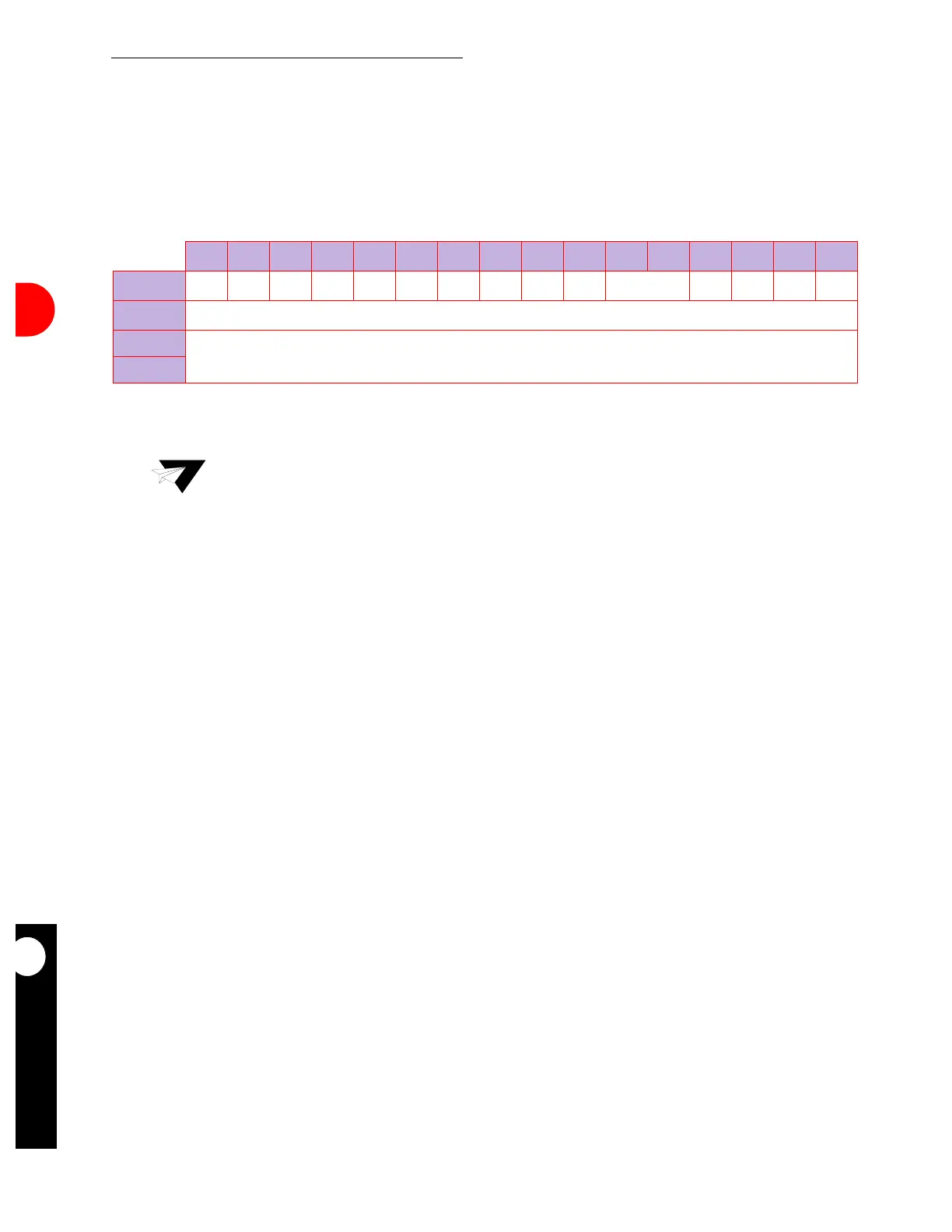
0 1 2 3 4 5 6 7 8 9 10 11 12 13 14 15
OFFSET + 0
E RES WI LFCM RES BRK BOF RES AB CR OV CD
OFFSET + 2
DATA LENGTH
OFFSET + 4
RX DATA BUFFER POINTER
OFFSET + 6
NOTE: You are only responsible for initializing the items in bold.
Note: The communication processor module sets all the status bits in this buffer
descriptor, but you must clear them before submitting the buffer descriptor to the
communication processor module.