Communication Processor Module
16-306 MPC823e REFERENCE MANUAL MOTOROLA
COMMUNICATION
16
SCCs
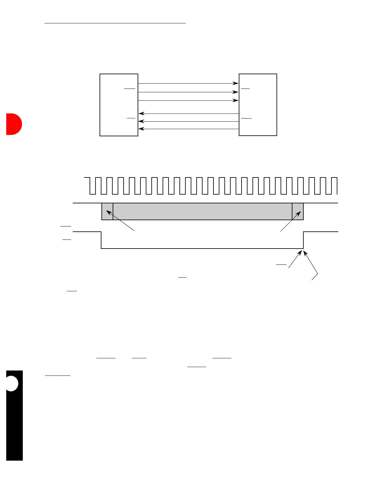
16.9.21.4.3 Transparent Synchronization Example. Figure 16-105 illustrates an
example of synchronization using the external signals.
MPC823e A and B in Figure 16-105 exchange transparent frames and synchronize each
other using the RTSx
and CDx pins. However, the CTSx pin is not required since
transmission begins at any time. Thus, the RTSx
pin is directly connected to the other
C
CDxD pin. The RSYN bit in the GSMR_H is not set and transmission and reception from
each MPC823e is independent.
MPC823e (A) MPC823e (B)
Figure 16-104. Sending Transparent Frames Between Each MPC823e
TXDx
RTSx
FIRST BIT OF FRAME DATA
LAST BIT OF FRAME DATA OR CRC
BRGOx
(OUTPUT
IS CLKx
INPUT)
(OUTPUT
IS RXDx
INPUT)
(OUTPUT
IS CDx
INPUT)
NOTES:
1. CTSx should be configured as always asserted in the port C parallel I/O or externally connected to ground.
2. The required GSMR_x configurations are DIAG = 00, CTSS = 1, CTSP is a "don't care", CDS = 1, CDP = 0, TTX = 1, and
TRX = 1. REVD and TCRC are application-dependent.
3. The transparent frame contains a CRC if the TC bit is set in the TX buffer descriptor.
TXDx
RTSx
RXDx
CDx
CDx
RTSx
TXDx
RXDx
BRGOx
CLKx
NOTES:
1. Each MPC82x generates its own transmit clocks. If the transmit and receive clocks are the same, one
MPC82x can generate transmit and receive clocks for the other MPC82x. For example, CLKx on MPC82x (B) could be used to
clock the transmitter and receiver.
BRGOx
CLKx
CDx LOST CONDITION TERMINATES RECEPTION OF FRAME
L = 1 IN TX BD CAUSES NEGATION OF RTSx
 Loading...

