Memory Map
MOTOROLA
MPC823e REFERENCE MANUAL
3-5
MEMORY MAP
3
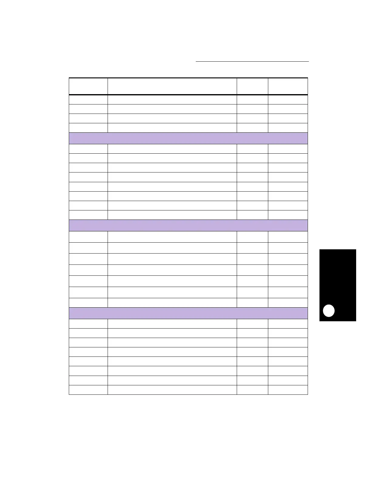
81C VFCR1—Video Frame Configuration Register (Set 1) 32
19-13
820 VFAA1—Video Frame Buffer A Start Address Register (Set 1) 32
19-14
824 VFBA1—Video Frame Buffer B Start Address Register (Set 1) 32
19-15
828 to 83F RES—Reserved —
—
LCD CONTROLLER
840 LCCR—LCD Panel Configuration Register 32
18-21
844 LCHCR—LCD Horizontal Control Register 32
18-23
848 LCVCR—LCD Vertical Configuration Register 32
18-25
84C to 84F RES—Reserved —
—
850 LCFAA—LCD Frame Buffer A Start Address 32
18-27
854 LCFBA—LCD Frame Buffer B Start Address 32
18-28
858 LCSR—LCD Status Register 8
18-29
859 to 85F RES—Reserved — —
I
2
C CONTROLLER
860
I2MOD—I
2
C Mode Register
8 16-468
864
I2ADD—I
2
C Address Register
8 16-473
868
I2BRG—I
2
C Baud Rate Generator Register
8 16-474
86C
I2COM—I
2
C Command Register
8 16-474
870
I2CER—I
2
C Event Register
8 16-475
874
I2CMR—I
2
C Mask Register
8 16-476
875 to 8FF RES—Reserved — —
DMA CONTROLLER
900 to 903 RES—Reserved — —
904 SDAR—SDMA Address Register 32 16-89
908 SDSR—SDMA Status Register (DSP Interrupts) 8 16-87
909 to 90B RES—Reserved — —
90C SDMR—SDMA Mask Register (DSP Interrupts) 8 16-34, 16-88
90D to 90F RES—Reserved — —
910 IDSR1—IDMA1 Status Register 8 16-94
911 to 913 RES—Reserved — —
Table 3-1. MPC823e Internal Memory Map (Continued)
INTERNAL
ADDRESS REGISTER
SIZE
(IN BITS)
PAGE NUMBER
LOCATION