Communication Processor Module
16-360 MPC823e REFERENCE MANUAL MOTOROLA
USB
COMMUNICATION
16
PROCESSOR MODULE
The V bit is set if the SOF token was received error-free.
• RBASE and TBASE—The receive and transmit buffer descriptor base address entries
define the starting point in the dual-port RAM for the set of buffer descriptors to receive
and transmit data. This provides a great deal of flexibility in partitioning the buffer
descriptors for the USB controller. By setting the W bit in the last buffer descriptor in
each list, you can select how many buffer descriptors to allocate for the transmit and
receive side of the USB controller. However, you must initialize these entries before
enabling the USB controller. Furthermore, you must not configure buffer descriptor
tables of the USB to overlap any other serial channel’s buffer descriptors or erratic
operation will occur.
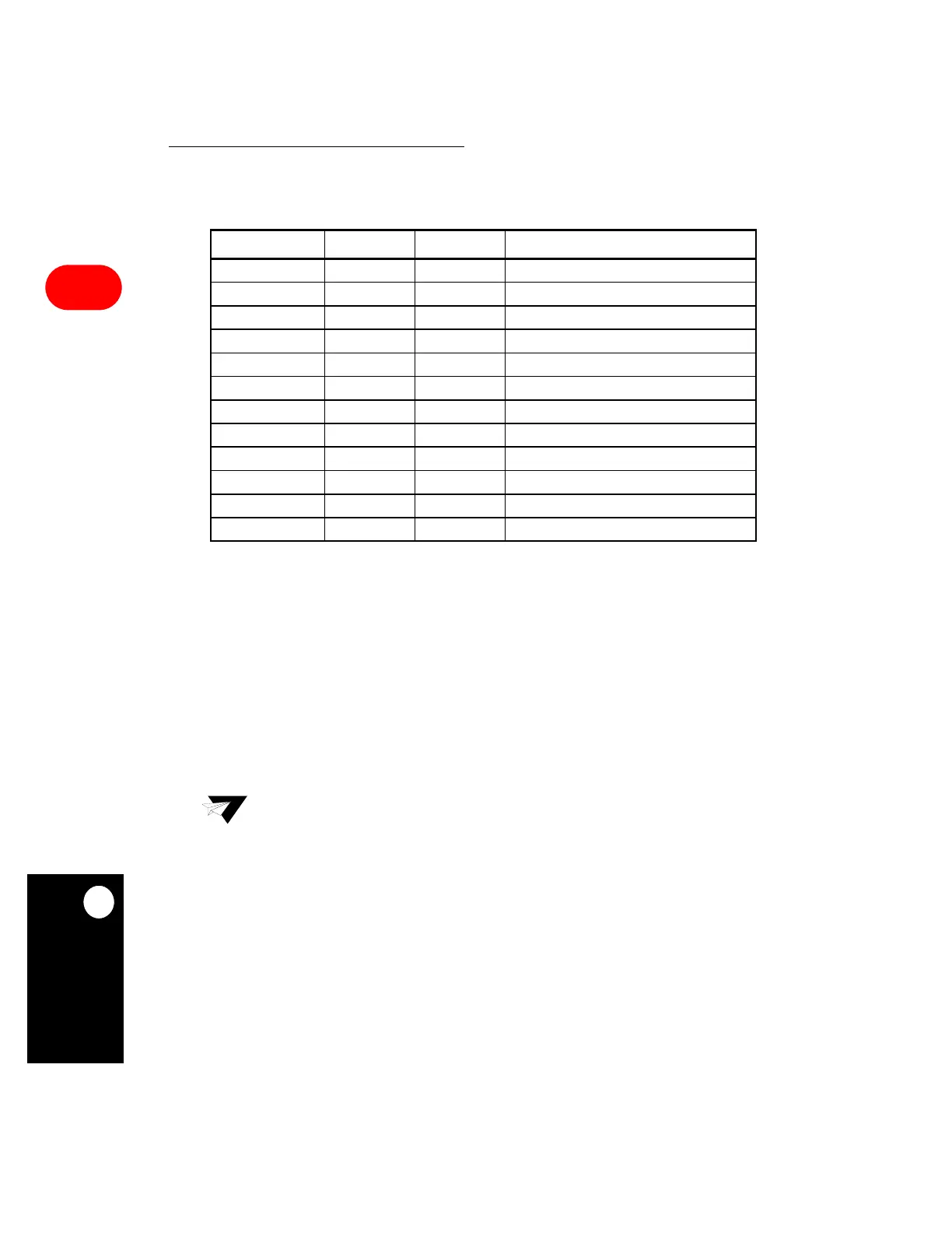
Table 16-35. Endpoint Parameters Block
ADDRESS NAME WIDTH DESCRIPTION
Base + 00 RBASE Half Word RX Buffer Descriptor Base Address
Base + 02 TBASE Half Word Tx Buffer Descriptor Base Address
Base + 04 RFCR Byte RX Function Code
Base + 05 TFCR Byte TX Function Code
Base + 06 MRBLR Half Word Maximum Receive Buffer Length
Base + 08 RBPTR Half Word RX Buffer Descriptor Pointer
Base + 0a TBPTR Half Word TX Buffer Descriptor Pointer
Base + 0c TSTATE Word TX Internal State
Base + 10 TPTR Word TX Internal Data Pointer
Base + 14 TCRC Half Word TX Temp CRC
Base + 16 TBCNT Half Word TX Internal Byte Count
Base + 18 RES 8 Bytes Reserved
NOTE: You are only responsible for initializing the items in bold. Also, Base = (EP x PTR).
Note: RBASE and TBASE must contain a value that is divisible by eight.
 Loading...

