Communication Processor Module
MOTOROLA MPC823e REFERENCE MANUAL 16-365
USB
COMMUNICATION
16
PROCESSOR MODULE
16.10.8 USB Controller Programming Model
16.10.8.1 USB MODE REGISTER. The read/write USB mode (USMOD) register controls
the USB controller’s operation mode.
LSS—Low-Speed Signaling
When set, this bit selects low-speed (1.5Mbps) signaling. The actual bit rate depends on the
USB clock source.
0 = Full-speed (12Mbps) signaling. Normal operation mode.
1 = Low-speed (1.5Mbps) signaling. This mode can be used for a point-to-point
connection to a low-speed device or in local loopback mode.
RESUME—Generate Resume Condition
When set, this bit generates a resume condition on the USB. This bit must be used if the
function wants to exit suspend mode.
Bits 2–4—Reserved
These bits are reserved and must be set to zero.
TEST—Test Mode
0 = Normal operation.
1 = Local loopback mode. In this mode, if the HOST bit is set, endpoint 0 operates as
host and endpoints 1–3 can be used as function endpoints.
HOST—Host Mode
0 = The USB controller implements a USB function.
1 = The USB controller implements a USB host. Endpoint 0 operates as the host. The
other endpoints are not used, unless the TEST bit is set.
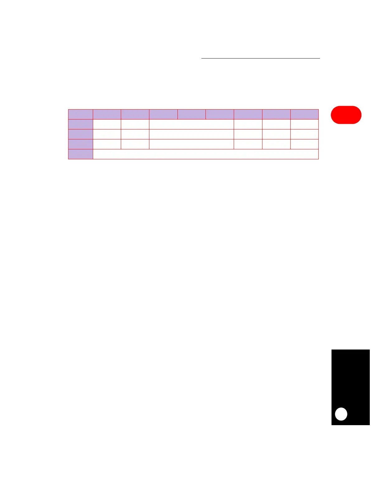
USMOD
BIT 0 1 2 3 4 5 6 7
FIELD LSS RESUME RESERVED TEST HOST EN
RESET 00 0 000
R/W R/W R/W R/W R/W R/W R/W
ADDR (IMMR & 0xFFFF0000) + 0xA00
 Loading...

