Communication Processor Module
MOTOROLA MPC823e REFERENCE MANUAL 16-399
SMC
COMMUNICATION
16
PROCESSOR MODULE
PM—Parity Mode
0 = Odd parity.
1 = Even parity.
SM—SMCx Mode
00 = GCI or SCIT support.
01 = Reserved.
10 = UART mode (must be selected for SMCx UART operation).
11 = Totally Transparent mode.
DM—Diagnostic Mode
00 = Normal mode.
01 = Local loopback mode.
10 = Echo mode.
11 = Reserved.
TEN—SMCx Transmit Enable
0 = SMCx transmitter disabled.
1 = SMCx transmitter enabled.
REN—SMCx Receive Enable
0 = SMCx receiver disabled.
1 = SMCx receiver enabled.
16.11.6.11 SMCx UART RECEIVE BUFFER DESCRIPTOR. Using the buffer descriptors,
the communication processor module reports information about the received data on a
per-buffer basis. It then closes the current buffer, generates a maskable interrupt, and starts
receiving data into the next buffer when one of the following events occurs:
• An error is received while a message is being processed.
• A full receive (RX) buffer is detected.
• A programmable number of consecutive idle characters are received.
Note: The communication processor module sets all the status bits in this buffer
descriptor, but you must clear them before submitting the buffer descriptor to the
communication processor module.
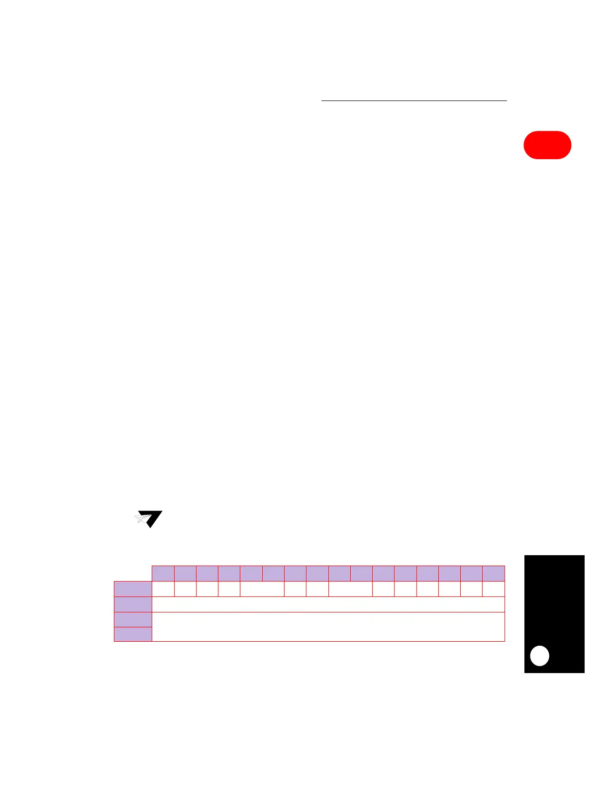
0 1 2 3 4 5 6 7 8 9 10 11 12 13 14 15
OFFSET + 0
E RES WIRESERVED CM ID RESERVED BR FR PR RES OV RES
OFFSET + 2
DATA LENGTH
OFFSET + 4
RX DATA BUFFER POINTER
OFFSET + 6
NOTE:
You are only responsible for initializing the items in bold.
 Loading...

