Communication Processor Module
16-496
MPC823e REFERENCE MANUAL
MOTOROLA
PORTS
COMMUNICATION
16
PROCESSOR MODULE
16.14.10 Port D Pin Functionality
The 13 port D pins are independently configured as general-purpose I/O pins if the
corresponding port D pin assignment register (PDPAR) is cleared. They are configured as
dedicated on-chip peripheral pins if the corresponding PDPAR bit is set.
As a general-purpose I/O pin, the signal direction is determined by the corresponding control
bit in the port D data direction register (PDDIR). The port I/O pin is configured as an input if
the corresponding PDDIR is cleared and it is configured as an output if the corresponding
PDDIR is set. All PDPAR and PDDIR pins are cleared at total system reset, which
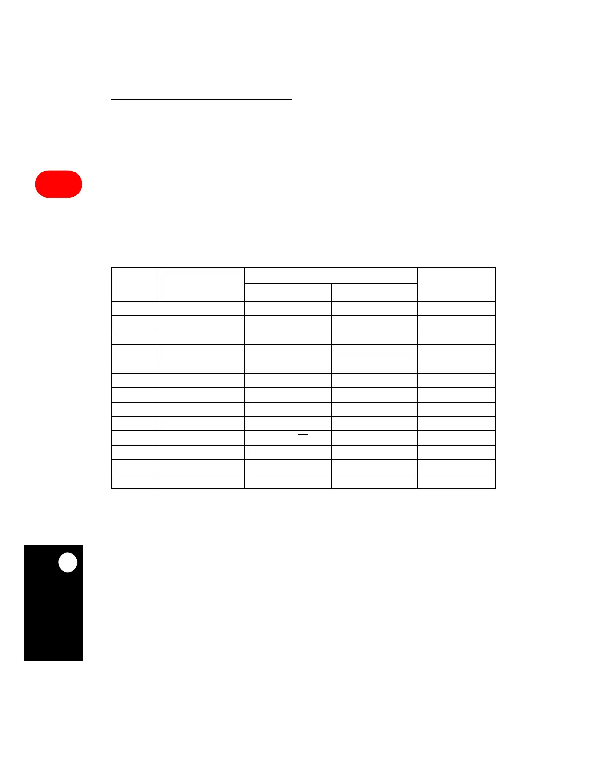
configures all port D pins as general-purpose input pins. Refer to Table 16-44 for all the
port D pin options’ default descriptions.
Table 16-44. Port D Pin Assignment
SIGNAL PDPAR = 0
PDPAR = 1
INPUT TO ON-CHIP
PERIPHERALS
PDDIR = 1 PDDIR=0
PD15 PORT D15 LD8 VD7
PD14 PORT D14 LD7 VD6
PD13 PORT D13 LD6 VD5
PD12 PORT D12 LD5 VD4
PD11 PORT D11 LD4 VD3
PD10 PORT D10 LD3 VD2
PD9 PORT D9 LD2 VD1
PD8 PORT D8 LD1 VD0
PD7 PORT D7 LD0 FIELD
PD6 PORT D6 LCD_AC/OE
BLANK
PD5 PORT D5 FRAME/VSYNC VV
PD4 PORT D4 LOAD/HSYNC VH
PD3 PORT D3 SHIFT/CLK VCLK VCC