PCMCIA Interface
MOTOROLA
MPC823e REFERENCE MANUAL
17-7
PCMCIA INTERFACE
17
17.4 PCMCIA OPERATION
17.4.1 Memory-Only Cards
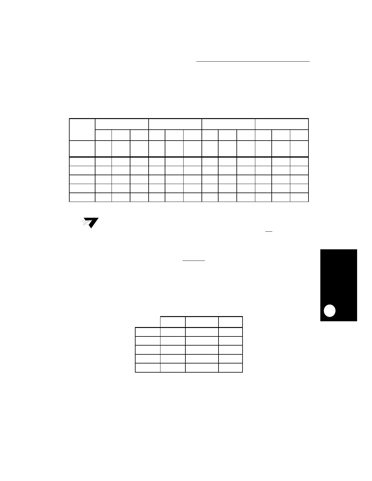
Table 17-2 shows a worst case example of host programming.
Table 17-2 assumes you are not using the WAIT_B
signal. If you are using it, then the
minimum strobe time is at least 35ns + 1 system clock.
17.4.2 I/O Cards
Table 17-3 shows a worst case example of programming PCMCIA host for I/O cycle.
Setup time worst case is for write, so setup = data_setup_before_IORD +1 system clock.
Table 17-2. Host Programming for Memory Cards
MEMORY
ACCESS
TIME
600NS 200NS 150NS 100NS
STP LNG HLD STP LNG HLD STP LNG HLD STP LNG HLD
CLK
CYCLE
100 300 150 30 120 90 20 80 75 15 60 50
20ns 6 24 8 2 8 5 2 6 4 1 4 3
30ns 4 16 5 2 5 3 1 4 3 1 3 2
40ns 3 12 4 1 4 3 1 3 2 1 2 2
62ns 2 8 3 1 2 2 1 2 2 1 1 1
83ns 2 6 2 1 2 2 1 1 1 1 1 1
Note:
Because the minimum hold time is one clock, the real access time is access time
plus one clock. Hold time and setup time HLD and STP, in this table, are the read
or write worst case. The worst case hold time is data disable from OE
. The worst
case setup time is address to strobe. Length (LNG) is the minimum strobe time.
Table 17-3. Host Programming For I/O Cards
STP(1) LNG HLD
20ns 4 8 2
30ns 3 6 1
40ns 3 4 1
62ns 2 3 1
83ns 2 2 1