LCD Controller
18-2
MPC823e REFERENCE MANUAL
MOTOROLA
LCD CONTROLLER
18
18.1.1 LCD Technology
A liquid crystal display (LCD) implements a low-power display technology that uses ambient
light to display images. LCDs consist of two pieces of glass with electrodes printed on the
inside and polarizers are used on the external front and rear surfaces. When the LCD is off,
no voltage is applied to the electrodes and light passes through the LCD. When it is on,
voltage is applied to the electrodes and the liquid crystal molecules align themselves in the
direction of the electric field. This causes the light to be blocked and out of phase with the
polarizers, which creates a dark area on the LCD. This darkness is a function of the RMS
voltage applied to them. The polarity of the applied voltage is not important and no DC bias
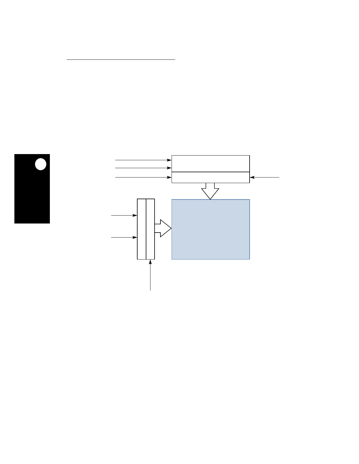
is allowed. A typical monochrome LCD module is illustrated in Figure 18-1 below.
The Y drivers apply high voltage to one row at a time. At the same time, the X drivers
connect the dark pixels to the opposing voltage and bright pixels to the same voltage as the
row. The value of each pixel is shifted by the shift register and latched when the whole row
is ready. While one row is being refreshed, the next row is being shifted in and each row is
refreshed at a rate inverse to the number of rows. If the number of rows is large, then the
refresh rate might become too small. When this occurs, the panel is divided into two sections
(upper and lower). Then the X shift register, which is twice as long, works at twice the speed
to refresh two columns at the same time (one column in the upper section and one in the
lower section). The X shift register can be loaded 1, 2, 4, or 8 bits per shift.
Figure 18-1. LCD Panel
SHIFT REGISTER
LATCH AND (T/S) DRIVE
ONE-BIT-SHIFTER
640 COLUMNS
480 ROWS
4 / 8 BITS
SHIFT
LATCH
PRESET
SHIFT
BACKPLANE (COMMON)
DRIVERS
FRONTPLANE
DRIVERS
SINGLE PANEL
X
Y
( +20V / 0V )
( 0V / +20V )
DATA
THREE-STATE
DISPLAY
 Loading...

