GENESYS User Manual Issue 1
Audio Monitoring Boards
Accessible from the rear of the console, the Monitor Boards handle the
Cue mixes, Inserts, Outputs and have various trims and system
connectors in place.
The majority of the signals that appear on the connectors on these boards
do not appear on the 25-way D-type connectors.
Regardless of the console size, all of the following four Monitor boards and
four rev returns will always be present in the same configuration.
Viewed from the rear, from Left to Right, these boards are:
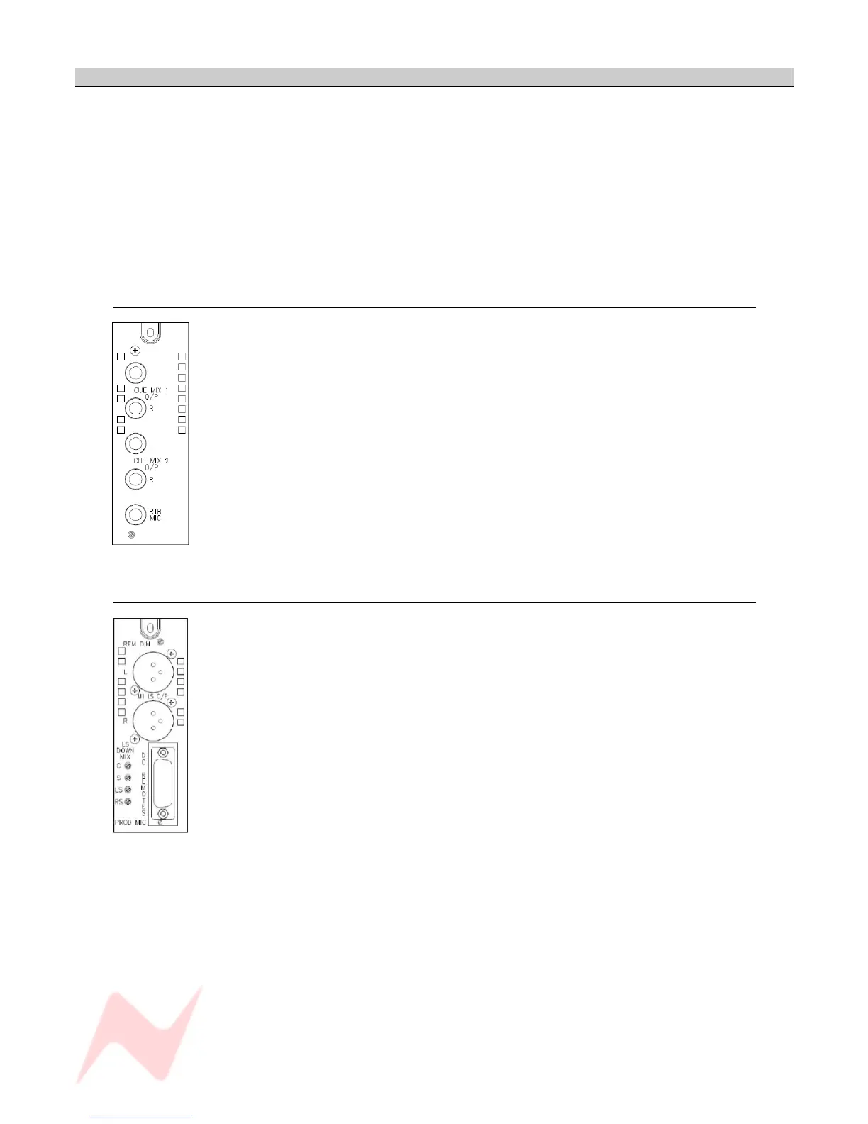
Monitor Board 1 (Cue mix)
Two jack sockets each handle the Left and Right of each Cue Mix.
There is also a jack socket for the Return Talkback mic, the adjacent trim
pot providing 0dB to +40dB of trim.
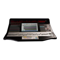
Monitor Board 2 (M1 L/S )
The 15-way D-type female socket fitted to Monitor Board on the extreme
right hand rear of the console provides access to the DC Remote Control
functions of the console as well as the producers microphone level input.
The Red Light connections on pins 1 & 2 of the connector provide a relay
contact closure when the Red Light switch is operated.
The relay contacts have a maximum switching current rating of 2 amps
and should be used to drive an external relay of suitable contact rating.
Pin 14 provides a current limited (~100mA) 4.7v source.
Pin 15 (digital ground) is for use with external switch contact closures to
provide the following remote DC functions:
- 78 -


 To Next Page