GENESYS User Manual Issue 1
About this manual
This manual consists of:
• A section-by-section operational overview of all parts of the console surface
• Technical & physical specifications including power consumption, dimensions, weight and other
relevant information
• Section on the optional Automation system
• Section on the optional Recall software
• Schematics and reference drawings of D-Type pin-outs etc.
There is a Heading Index at the start of this manual, plus an Alphabetical Index, an Illustration Index and
an Index of Tables at the end.
There is also a table explaining the Acronyms and Abbreviations of the most commonly used buttons and
functions in this document.
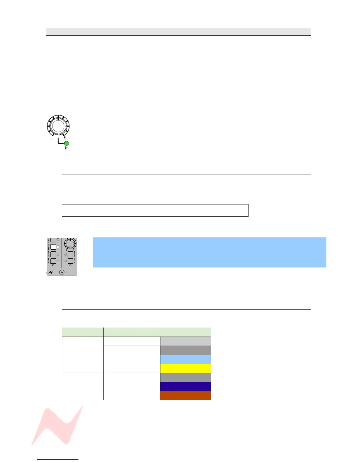
Some controls on the console have two functions (for example a rotary Pot provides a rotary
control, plus an On/Off push-switch to either enable the feature or provide a second
function).
Where relevant, the On/Off state (or second function) of the control is displayed by an
adjacent led.
Conventions used
All button names / rotary controls are shown in BOLD CAPITALS.
Any text regarding the interlocking of buttons is shown in plain Italics.
All text regarding the optional audio processing cassettes is framed.
> An arrow-shaped bullet-point indicates you should do this action.
All text regarding SEL Mode is shown with a blue background.
All diagrams illustrating SEL Mode functionality, will have unavailable functions and leds
greyed out (left).
Console surface colour coding
The knobs and buttons on the Channel Strip and 8T sections of the console are colour-coded for
ease of operation.
Type Control Colour
Button
Channel Input Light Grey
Monitor Input Dark Grey
Auxiliary Light Blue
SEL Yellow
Rotary
Level Control Dark Grey
Pan Dark Blue
Gain Dark Red
- 9 -