VBA23001-R.3762.A
- A46 ・ D90 -
Device
J19004-1
DIAL INDICATOR AND STAND
J18001-1
BODY BACK FOCUS GAUGE
3.
2.
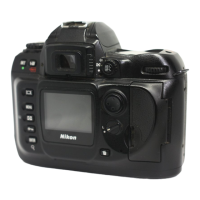
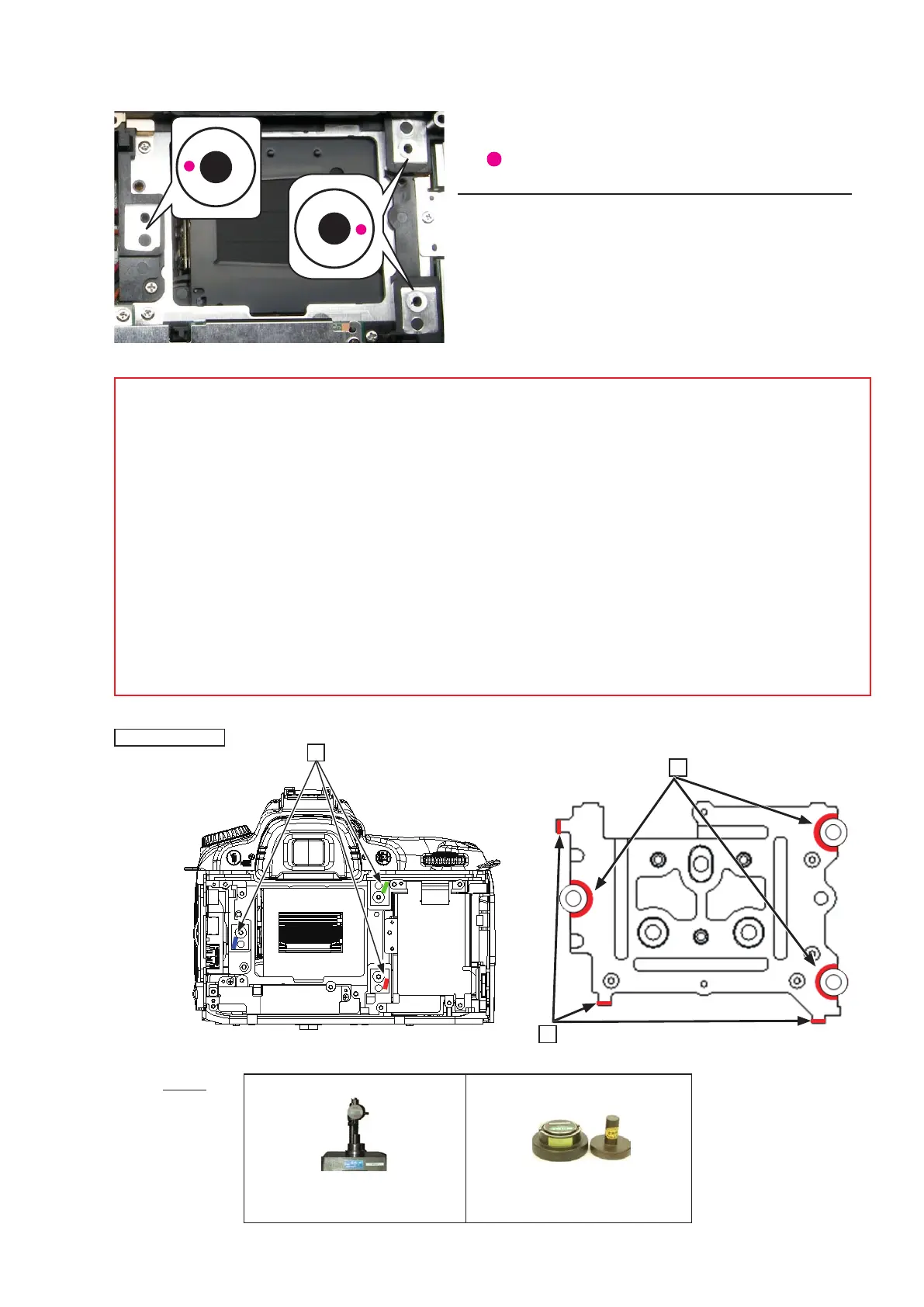
・ Measure six places from the bayonet face to the image
PCB attaching face.
○ mark: to be measured
Standard: 48.49±0.015mm / Parallelism: 0.015mm or less
・ In case the result is out of standard, make an adjustment
by putting the washers between the front body and the
rear body.
1.
Note: For some bodies, the washer(s) is/are already put on the attaching face of the image PCB . There
is a red mark indication at the following three positions.
1. Indication: on the attaching face of the camera body side
Purpose
:
To adjust the height of the camera body
2. Indication: on the attaching face of the image PCB side
Purpose
:
To adjust the height of the image PCB
3.Indication: at the corner edge on the attaching face of the image PCB side
Purpose: To adjust and position the image PCB
Therefore, in case of the above 1., when the camera body is disassembled or the image PCB is replaced,
put the washer at the original position. In case of the above 2 and 3, when the image PCB is replaced,
remove the washer.
Mark indication
 Loading...