E Series Automated Dispensing System
122 www.nordsonefd.com info@nordsonefd.com 800-556-3484 Sales and service of Nordson EFD dispensing systems are available worldwide.
DXF Screen and Icons (continued)
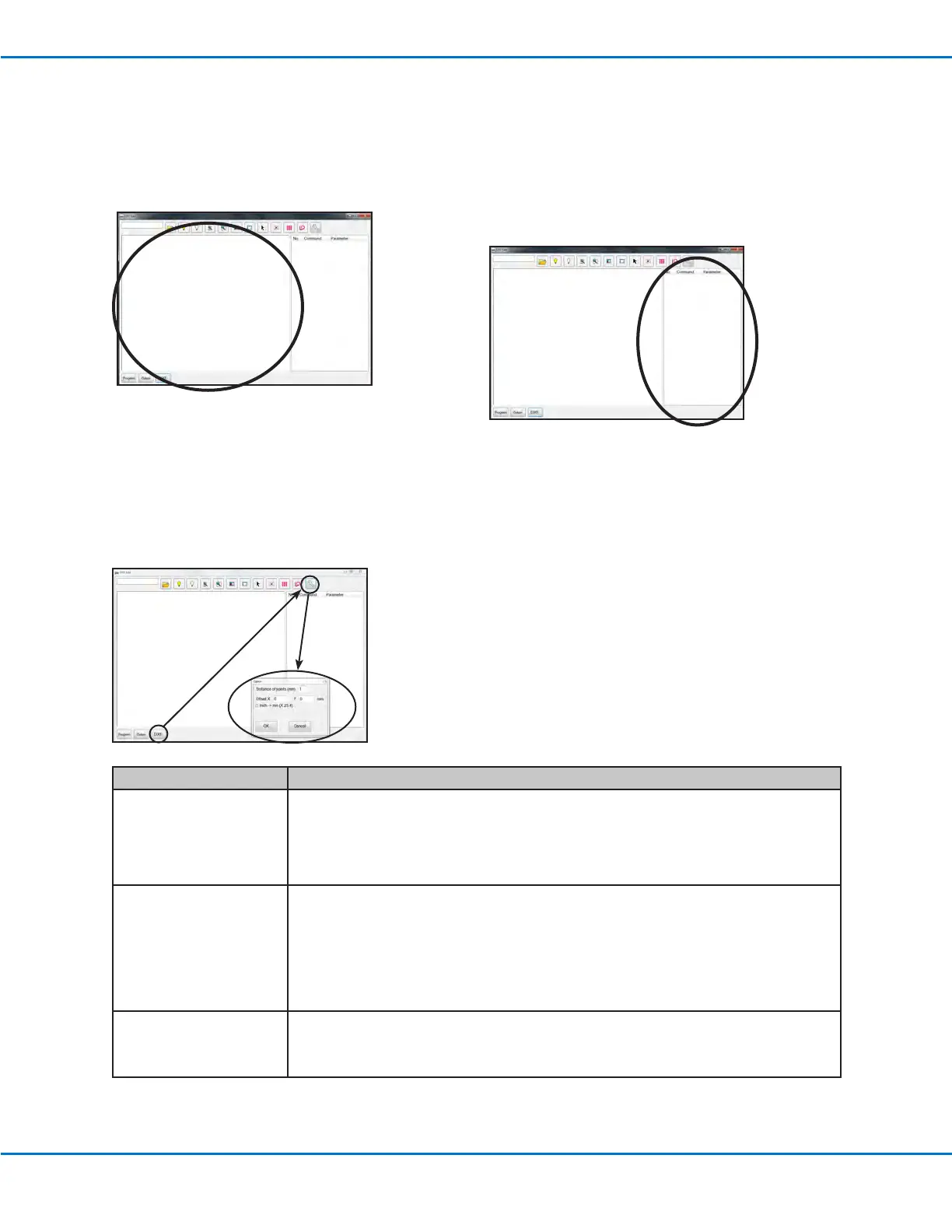
2. DXF Screen Drawing Window
After a DXF is imported, it appears in the DXF screen
drawing window so you can select the drawing
elements you want to include in the dispense program.
3. DXF Screen Command Window
Once the elements are selected and then either the
Point Dispense or the Line Dispense icon is clicked,
the pattern information is converted into commands
with coordinates. The commands are shown in the DXF
screen command window.
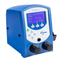
4. DXF Screen Option Window
The DXF screen Option window is used to customize how a DXF le imports, thus improving the subsequent
imported result. Refer to “Modifying the DXF Import Options” on page123 for the procedure for using this screen
to improve DXF import results.
Item Description
Distance of points (mm) Species the distance between any two points on a curve when the curve is converted to
coordinates.
EXAMPLE: When this value is set to 1 and a 10-mm long curve is converted to commands, the
result will be a series of Line Start, Line Passing, and Line End commands that will produce a
curve with a total of 11 points.
Offset X, Y After you generate program commands for an imported le (done by clicking the Point Dispense
or Line Dispense icon), the resulting XY values may be a negative number. This causes the
imported points to display off the grid window. To resolve this issue, you can enter X and / or Y
values in these offset elds to cause the imported XY values to change to positive values.
EXAMPLE: If an imported XY value is -150, -150, 0, enter 200 for Offset X and 200 for OffsetY,
click OK and then click the Point Dispense or Line Dispense icon to refresh the values. The new
values will be 50, 50, 0 and the points will be visible on the grid window on the Program screen.
Inch -> mm (X 25.4) Causes the system to convert inches to millimeters upon DXF le import.
EXAMPLE: If the source DXF has the length units set to inches, check this box to convert the
drawing from inches to millimeters when it is imported.