E Series Automated Dispensing System
41www.nordsonefd.com info@nordsonefd.com 800-556-3484 Sales and service of Nordson EFD dispensing systems are available worldwide.
Setting the Tool Offset
If your system includes a camera or similar accessory installed on the Z axis, follow this procedure to teach the
system the offset values. The offset values represent the distance between the tip and the accessory.
PREREQUISITES
The accessory and the valve system are properly installed.
The XYZ offset values (in mm) needed for this function are calculated.
# Key Press Step Teach Pendant Display
1
> >
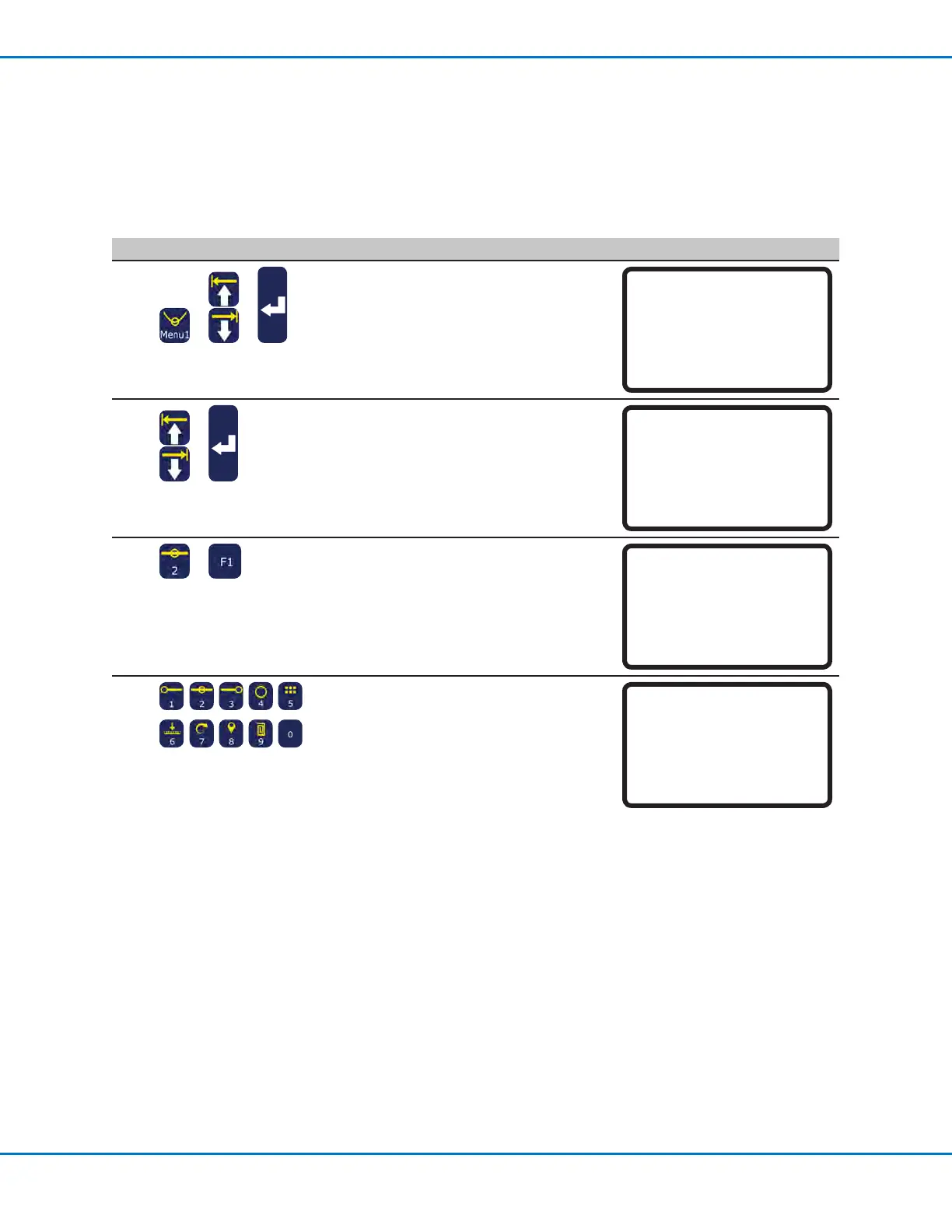
• Press MENU1.
• MOVE UP / DOWN to UTILITY MENU.
• Press ENTER.
[MENU 1] 2/2
08*Utility Menu
09 Diagnostic
2
>
• MOVE UP / DOWN to MEMORY.
• Press ENTER.
[UTILITY] 1/1
01 Program
02*Memory
03 Key Beep
04 Online Signals
05 Barcode Scanner
06 System Lockout
3
>
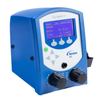
• Press 2 TOOL OFFSET.
• Press F1 to enter the offset values that
represent the distance between the tip
and the accessory.
Memory Utility
------------------------------
1 Clear Memory
2 Tool Offset
Select: _
[F1] OK
4
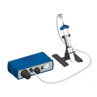
• Enter the offset values (in mm) for
OffsetX, Offset Y, and Offset Z.
Refer to the example below to see how
to calculate the offset values.
Tool Offset
------------------------------
Offset X: 0.00 mm
Offset Y: 0.00 mm
Offset Z: 0.00 mm
[F1] OK
Example of How to Calculate Tool Offset Values
In this example, the accessory is a camera that has been installed on the robot. Using the camera, create a dispense
dot on the workpiece and record the XYZ coordinates. Next, move the tip to the same location on the workpiece,
create a dispense dot, and record the XYZ coordinates. Calculate the difference between the two coordinates to
obtain the offset values as follows:
• Accessory XYZ values: 10 20 5
• Tip XYZ values: 8 22 15
• Offset XYZ values: 2 -2 -10 (the differences between the accessory XYZ values and
the tip XYZ values)