9-1-5
Starting and Stopping Tag Data Links
Tag data links are automatically started when the data link parameters are downloaded from the Net-
work Configurator
and the power supply to the CPU Unit is turned ON.
Thereafter
, you can start and stop tag data links for the entire network or individual devices from the
Network Configurator. Starting and stopping tag data links for individual devices must be performed for
the originator.
Furthermore, you can execute instructions from the user program to start and stop the entire network.
Refer to 9-2-12 Starting and Stopping Tag Data Links on page 9-61 for details.
9-1-6
Controller Status
You can include the Controller status as a member of a tag set in the data sent and received.
The Controller status is a set of flags that indicate the operating status of the CPU Unit (operating in-
formation, error information, Controller error level).
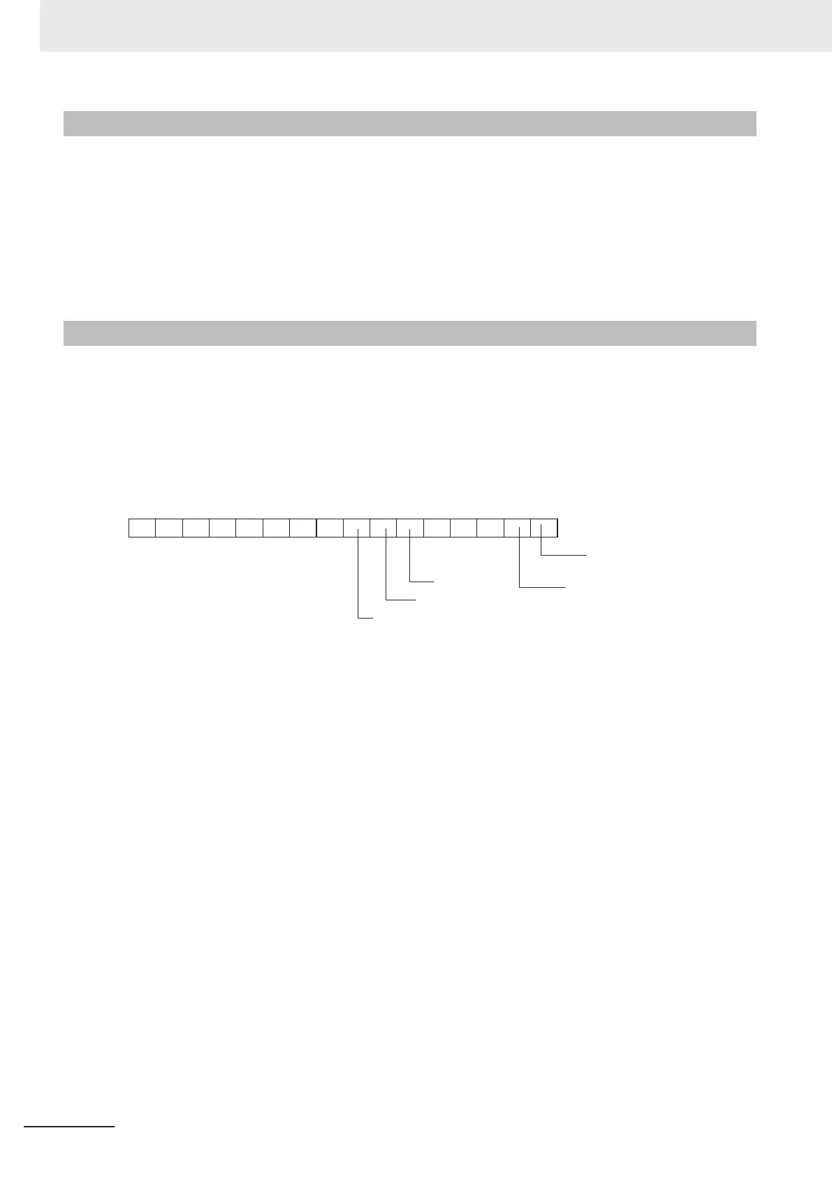
If the Controller status is specified as an output (produce) tag, the Controller status is added to the
start of the tag set in the following format.
(Select the Include Option for Controller Status in the upper right of the Edit T
ag Set Dialog Box.)
15 14 13 12 11 10 9 8 7 6 5 4 3 2 1 0
0 0 0 0 0 0 0 0 0 0 0
Major fault level
Contro
ller error
Partial fault level Controller error
Minor fault level
Controller error
Controller Error Flag
Controller Operating Flag
Note Of the flags in bits 5 to 7 that indicate the current error level, only the flag for the highest error level changes
to TRUE.
For example, if a minor fault level Controller error and a major fault level Controller error occur at the same
time, only the flag for the major fault level Controller error (bit 7) will change to TRUE and the flag for the
minor fault level Controller error (bit 5) will remain as FALSE.
T
o receive the Controller status, specify the Controller status for the In - Consume Tab Page in the
dialog box used to edit the receive tag set.
(Select the Include Option for Controller Status in the upper right of the Edit Tag Set Dialog Box.)
When a tag data link is started, the contents of the Controller status is stored in the device variables
that are given below.
• CIP Communications1 Target PLC Operating Mode: EIP_Comm1Status.TargetPLCModeSta[255]
• CIP Communications2 Target PLC Operating Mode: EIP_Comm2Status.TargetPLCModeSta[255]
• CIP Communications1 Target PLC Error Information: EIP_Comm1Status.TargetPLCErr[255]
• CIP Communications2 Target PLC Error Information: EIP_Comm2Status.TargetPLCErr[255]
Example: Using an NX-series EtherNet/IP Unit with unit number 1 to send the CIP Communications1
Target PLC Operating Mode of the Target Node with an IP Address of 192.168.250.2
9 Tag Data Link Functions
9-10
NX-series EtherNet/IP Unit User's Manual (W627)

 Loading...


