5-3
Connecting to the Network
5-3-1
Ethernet Connectors
The following standards and specifications apply to the connectors for the Ethernet twisted-pair cable.
• Electrical specifications: Conforming to IEEE 802.3 standards.
• Connector structure: RJ45 8-pin Modular Connector (conforming to ISO 8877)
• For information on connecting shield wire to connector hoods, refer to 5-1-2 Ethernet Switch Types
on page 5-3.
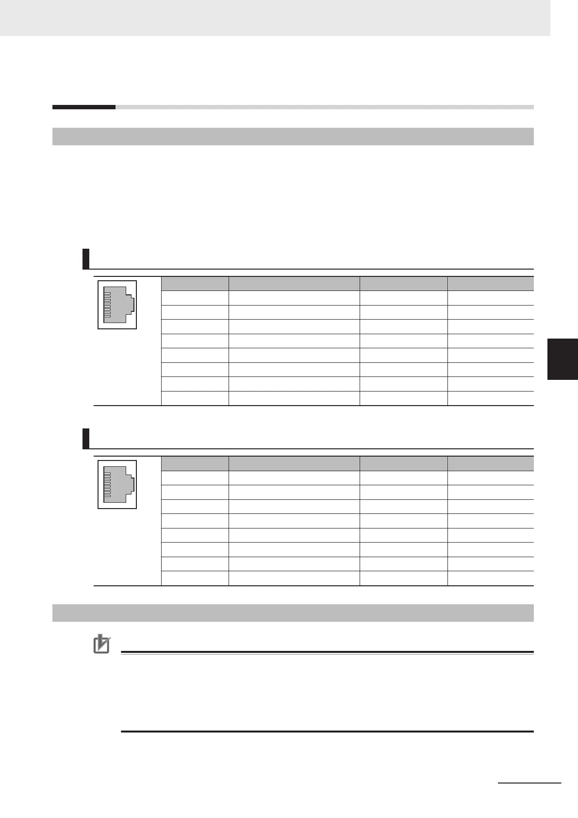
10Base-T and 100Base-TX
Connector pin Signal name Abbr. Signal direction
1 Transmission data + TD+ Output
2 Transmission data − TD− Output
3 Reception data + RD+ Input
4 Not used --- ---
5 Not used --- ---
6 Reception data − RD− Input
7 Not used --- ---
8 Not used --- ---
1000Base-T
Connector pin Signal name Abbr. Signal direction
1 Communication data DA+ BI_DA+ Input/output
2 Communication data DA− BI_DA- Input/output
3 Communication data DB+ BI_DB+ Input/output
4 Communication data DC+ BI_DC+ Input/output
5 Communication data DC− BI_DC− Input/output
6 Communication data DB− BI_DB− Input/output
7 Communication data DD+ BI_DD+ Input/output
8 Communication data DD− BI_DD− Input/output
5-3-2
Connecting the Cable
Precautions for Correct Use
• Turn OFF the Controller's power supply before connecting or disconnecting Ethernet commu-
nications cable.
• Allow extra space for the bending radius of the communications cable.
For the dimensions when the communications cable is connected to the Unit, refer to Installa-
tion Height
on page A-3. The required space depends on the communications cable and
connector that are used. Consult the manufacturer or sales agent.
1 Install the twisted-pair cable.
5 Installing Ethernet Networks
5-13
NX-series EtherNet/IP Unit User's Manual (W627)
5-3 Connecting to the Network
5
5-3-1 Ethernet Connectors

 Loading...


