14-6
Checking with the Network Configu-
rator
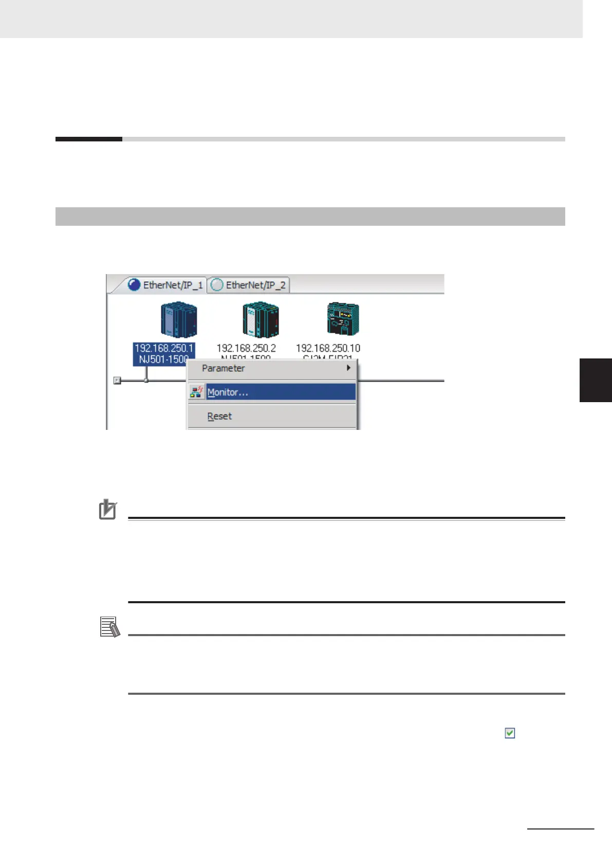
You can check the communications status of each device on the EtherNet/IP network (e.g. tag data
link connection status) with the Network Configurator.
14-6-1
The Network Configurator's Device Monitor Function
Connect the Network Configurator online, select the device to be checked, right-click to display the
pop-up menu, and select Monitor.
The Monitor Device Dialog Box will be displayed.
Precautions for Correct Use
Monitoring may not be performed if the following settings are configured on the NJ/NX-series
Controller on the connection route or on the destination NJ/NX-series Controller. If monitoring is
not performed, check the following settings. Refer to CIP Message Server
on page 7-15,
andPacket Filter on page 7-7 for details on the settings.
• The Do not use Option is selected for the CIP message server.
• The Use Option is selected for Packet Filter.
Additional Information
If a communications error occurs during monitoring, the dialog box will continue to show the last
information that was collected.
To start monitoring again, close the Monitor Device
Dialog Box, and then open the Monitor
Device Dialog Box again.
l
Status 1 Tab Page
The following check boxes are displayed for the status. If a check box is checked with
, the sta-
tus is TRUE.
14 Troubleshooting
14-47
NX-series EtherNet/IP Unit User's Manual (W627)
14-6 Checking with the Network Configurator
14
14-6-1 The Network Configurator's Device Monitor Function

 Loading...


