1-2
System Configuration
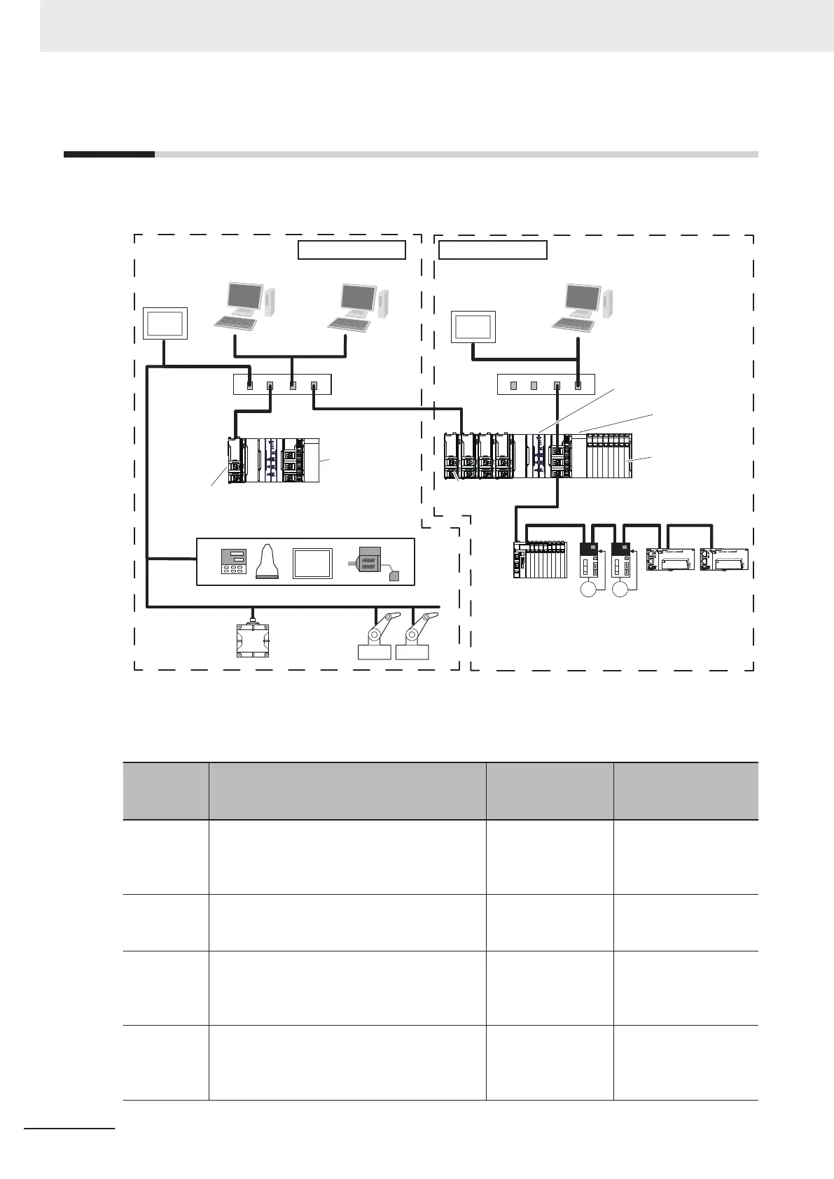
The following figure shows a configuration example for a system that uses the NX-series EtherNet/IP
Unit.
EtherCAT
Slave Terminal
Servo Drives
General-purpose
slaves
POWER
PORT2
POWER
PORT2
EtherNet/IP communications devices
RFID system
Sysmac Studio
Network Configurator
Sysmac Studio
Network Configurator
HOST PC
HMI
Ethernet
Switch
CIP Safety I/Os
FSoE I/O Units
NX I/O Units
Safety
CPU Unit
NX-series
EtherNet/IP Unit
NX-series
NX502 CPU Unit
HMI
Ethernet
Switch
NX-series
NX502 CPU Unit
NX-series
EtherNet/IP Units
Safety
CPU Unit
Process Controller Machine Controller
The following table shows the description, NX502 CPU Unit connection method, and quantity for each
configuration element in the figure above.
Configura-
tion element
Description
NX502 CPU Unit
connection meth-
od
Qty
NX502 CPU
Unit
A CPU Unit to which the NX-series EtherNet/IP
Unit is connected. This Unit performs machine
control and process control of the system.
--- One Unit for machine
control, and one Unit
for overall process con-
trol
NX-series
EtherNet/IP
Unit
One of X Bus Units which performs EtherNet/IP
communications.
X Bus Up to four Units per an
NX502 CPU Unit
NX I/O Unit An interface Unit to connect an NX-series CPU
Unit to control devices such as sensors and ac-
tuators. This Unit can also be connected to an
NX-series Communications Coupler Unit.
NX bus of CPU Unit
and Slave T
erminal
Zero to multiple Units
(depends on applica-
tion)
Safety CPU
Unit
A CPU Unit which controls the safety circuit of
manufacturing equipment. This Unit controls
both of the safety control within equipment by
FSoE and the line safety control by CIP Safety.
NX bus of CPU Unit One Unit per an NX502
CPU Unit
1 Features and System Configuration
1-6
NX-series EtherNet/IP Unit User's Manual (W627)

 Loading...


