9-3
Ladder Programming for Tag Data
Links
9-3-1
Ladder Programming for Tag Data Links
The following conditions 1 to 3 should be fulfilled if you use tag data link data for a ladder program-
ming. The additional conditions 4 and 5 should be also fulfilled if you input the Controller information of
the target node.
The device variables listed below assume that the communications port 1 of an NX-series EtherNet/IP
Unit with unit number 2 is used. N2 at the beginning of the device variable represents unit number 2.
Refer to Section 6 Device Variables Related to the NX-series EtherNet/IP Unit on page 6-1 for the
variable names of device variables when the communications port 2 is used.
l
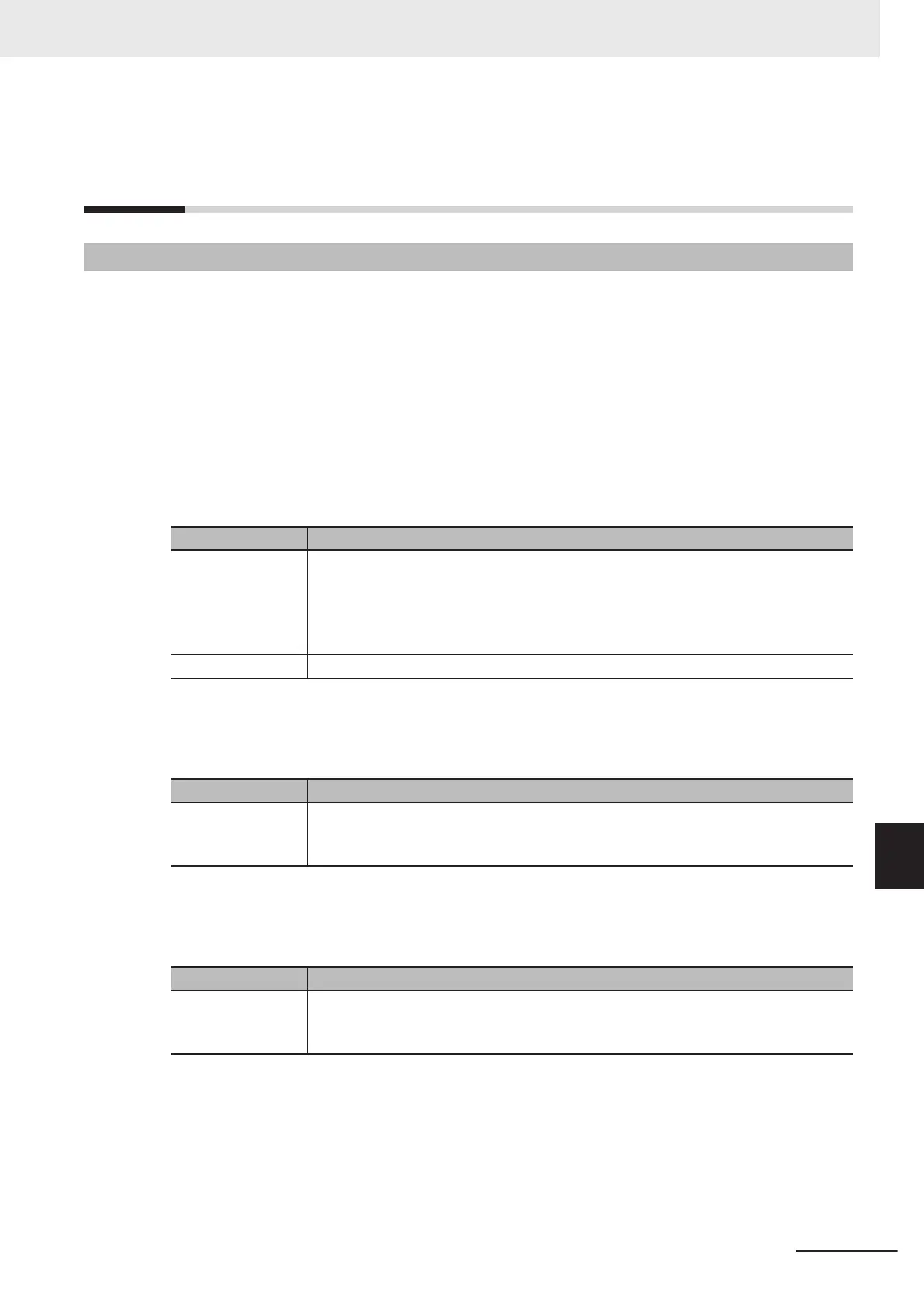
Conditions for Enabling Tag Data Links for the EtherNet/IP Port
The following conditions 1 and 2 should be both fulfilled.
No. Condition
1 The following error status bits in the N2_ETN_ErrSta
(Communications Port Error)
variable are F
ALSE.
• Major fault: Bit 7
• Partial fault: Bit 6
• Minor fault: Bit 5
2 The N2_ETN_Port1Status.EtnOnlineSta (Port1 Online) variable is TRUE.
l
Condition for Tag Data Links with Connection Established to the Target
Device
The following condition 3 should be fulfilled.
No. Condition
3 In the N2_EIP_Comm1Status.EstbTargetSta[255] (CIP Communications1 Normal T
ar-
get Node Information) variable, the bit corresponding to the target node address is
TRUE.
l
Condition of the Controller Operating Mode (Operating or Stopped) (Only
for OMRON Controllers)
The following condition 4 should be fulfilled.
No. Condition
4 In the N2_EIP_Comm1Status.TargetPLCModeSta[255] (CIP Communications1 T
arget
PLC Operating Mode) variable, the bit corresponding to the target node address is
TRUE.
l
Condition of the Controller Error Status (Fatal or Non-fatal Error) of the
Target Node (Only for OMRON Controllers)
The following condition 5 should be fulfilled.
9 Tag Data Link Functions
9-73
NX-series EtherNet/IP Unit User's Manual (W627)
9-3 Ladder Programming for Tag Data Links
9
9-3-1 Ladder Programming for Tag Data Links

 Loading...


