EasyManuals Logo

Omron NX Series User Manual

Omron NX Series
464 pages
To Next Page IconTo Next Page
To Previous Page IconTo Previous Page
Page #56 background imageLoading...
Page #56 background image
3-1
Part Names
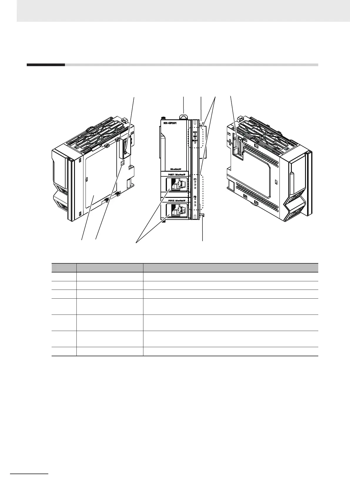
The following table gives the name of each part of the NX-series EtherNet/IP Unit.
(A) (C) (D) (A)(B)
(C)(E)(F)(G)
Symbol Name Function
A X Bus connectors These connectors are used to connect another Unit.
B DIN Track mounting hook This hook is used to mount the Unit to a DIN Track.
C Unit hookup guides These guides are used to connect two Units.
D Operation status indica-
tors
The indicators show the current operating status of the Unit.
E EtherNet/IP ports The communications ports for EtherNet/IP connection. There are two
ports.
F DIP switch This switch is for configuring internal settings of the Unit, but not used
normally
. Always keep all pins from SW1 to SW4 in OFF state.
G
Unit specifications The specifications of the Unit are given here.
3 Part Names and Functions
3-2
NX-series EtherNet/IP Unit User's Manual (W627)

Table of Contents

Other manuals for Omron NX Series

Questions and Answers:

Question and Answer IconNeed help?

Do you have a question about the Omron NX Series and is the answer not in the manual?

Omron NX Series Specifications

General IconGeneral
Programming LanguagesLadder, Structured Text, Function Block Diagram, Sequential Function Chart
Communication PortsEthernet, USB, RS-232C, RS-485
Memory CapacityVaries by model
Program MemoryVaries by model
Data MemoryVaries by model
Operating Temperature0°C to 55°C
Power Supply24 VDC
Ethernet Ports1 or 2 ports (depending on model)
USB Ports1 or 2 ports (depending on model)
DimensionsVaries by model
WeightVaries by model

Related product manuals