3-2
Part Functions
3-2-1
Operation Status Indicators
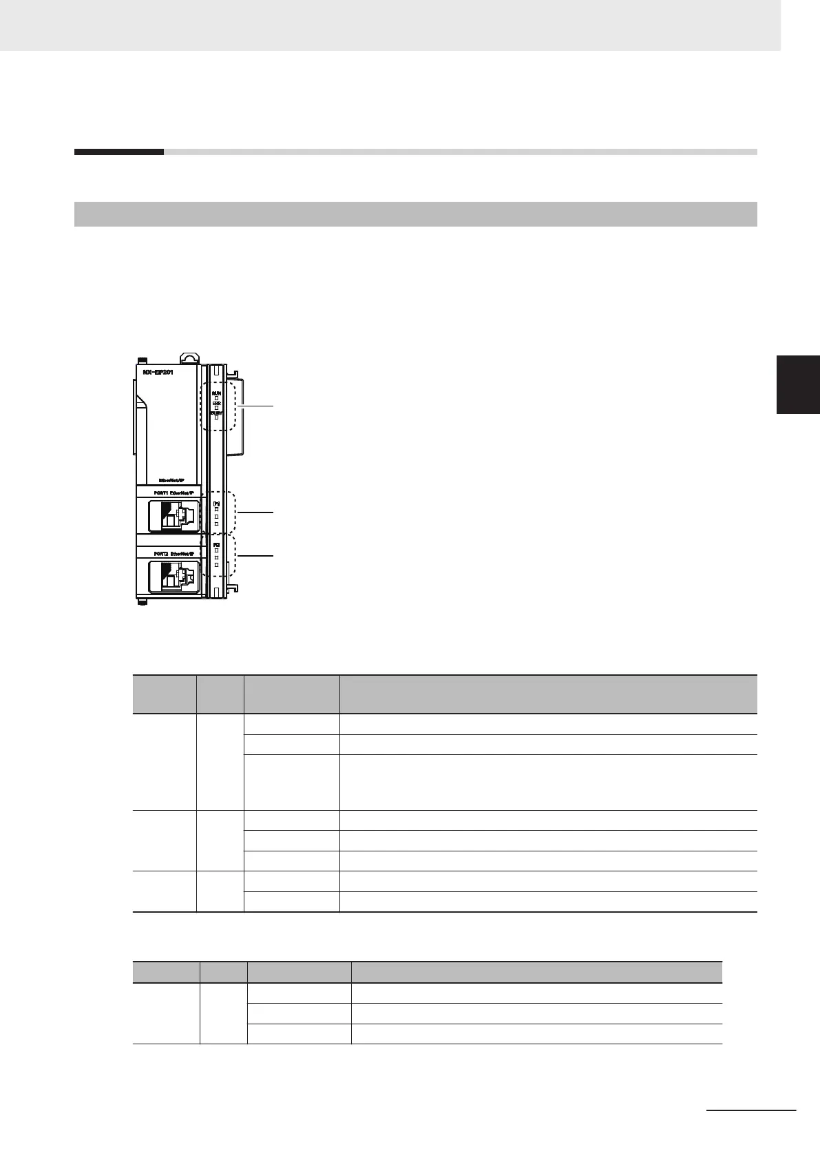
The operation status indicators include the Unit status indicators which display the operating status of
the NX-series EtherNet/IP Unit and the EtherNet/IP (Port 1/Port 2) status indicators which display the
status of EtherNet/IP ports.
The specifications of both instructions are given in the following table.
Unit Status Indicators
EtherNet/IP Status Indicators
Port 1
EtherNet/IP Status Indicators
Port 2
Unit Status Indicators
Indicator Color
Indicator sta-
tus
Status of NX-series EtherNet/IP Unit
RUN Green Lit Power is ON.
Flashing A System Initialization Error occurred.
Not lit Power is OFF, or a Power Supply Error, a Hardware Initialization Error, an
X Bus Unit Hardware Error, or an error for which the user cannot recover
operation occurred in the Unit.
ERR
Red Lit An error for which the user cannot recover operation occurred in the Unit.
Flashing An error for which the user can recover operation occurred in the Unit.
Not lit An error not occurred in the Unit.
BUSY Yellow Flashing Built-in non-volatile memory access in progress.
Not lit Other than the above.
EtherNet/IP (Port 1/Port 2) Status Indicators
Indicator Color Indicator status Status of EtherNet/IP port
NET RUN Green Lit Normal
Flashing Ethernet communications are in progress.
Not lit Ethernet communications are not possible.
3 Part Names and Functions
3-3
NX-series EtherNet/IP Unit User's Manual (W627)
3-2 Part Functions
3
3-2-1 Operation Status Indicators

 Loading...


