Route Path Notation
The route path describes the route from the source Controller to the destination Controller using the
network type number and destination address as follows.
Network type number\#Destination address\Network type number\#Destination address
Do not add # to the network type number
, and add # to the beginning of the destination address.
The meaning of network type number and destination address is described below.
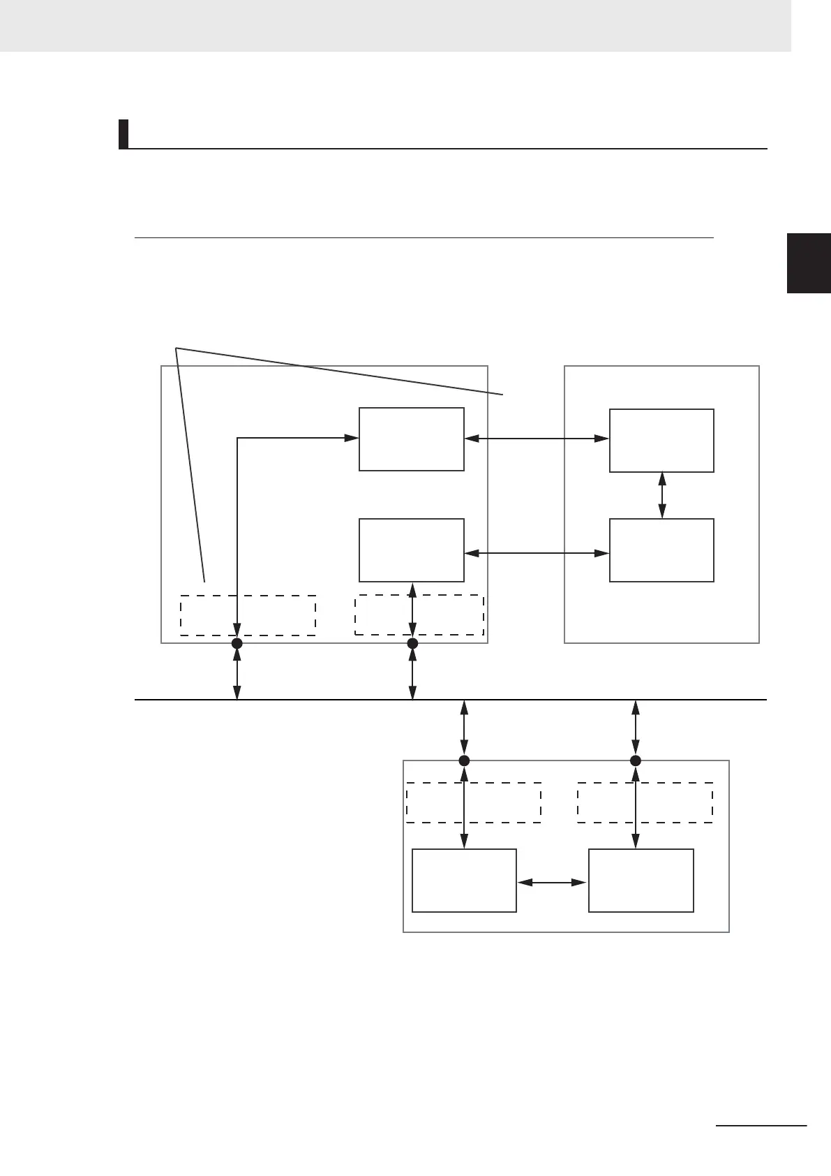
NX-EIP201 Unit Number 1
Back Plane
Port (#01)
Back Plane
Port (#01)
Back Plane
Port (#01)
EtherNet/IP Port 1
192.168.1.1
EtherNet/IP Port 2
192.168.2.1
Communications Port
(#02)
NX502 CPU Unit
CIP Protocol Stack 1
(Destination Address
00 hex)
CIP Protocol Stack 2
(Destination Address
01 hex)
CIP Protocol Stack 1
(Destination Address
10 hex)
CIP Protocol Stack 2
(Destination Address
11 hex)
Ethernet
Back Plane
Port (#01)
Network Type
Number
NX701 CPU Unit
CIP Protocol Stack 1
(Destination Address
00 hex)
CIP Protocol Stack 2
(Destination Address
01 hex)
EtherNet/IP Port 1
192.168.1.7
EtherNet/IP Port 2
192.168.251.1
Communications Port
(#02)
Communications Port
(#02)
Communications Port
(#02)
l
Network Type Number
A network type number is a number that is assigned to each port on the path to the destination
Controller. There are two types of port: backplane port and communications port.
10 CIP Message Communications
10-5
NX-series EtherNet/IP Unit User's Manual (W627)
10-2 Client Function of CIP Mes-
sage Communications
10
10-2-4 Route Path

 Loading...


