Chapter 3
Interrupts
III - 14 Overview
NMI Processing
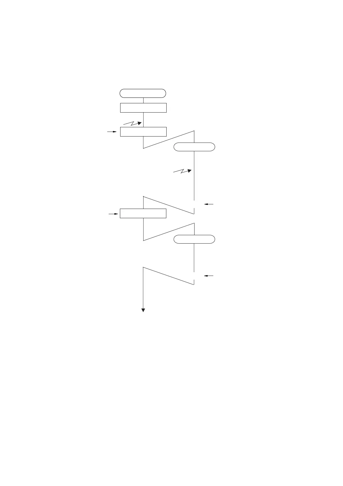
Figure:3.1.8 shows the processing sequence of NMI.
Figure:3.1.8 Processing Sequence for Non-Maskable Interrupt
IM1-0="00"
)
IM1-0="00"
)
IM1-0="11"
)
(
IM1-0="11"
)(
PSW.IM1-0="11"
*1
*2
RTI
RTI
Main Program
NMI 1 occurs
NMI 2 occurs
Interrupt acceptance cycle
Interrupt acceptance cycle
NMI handler: 1
NMI handler: 2
Parentheses () indicates hardware processing.
The multiple interrupts are not accepted during NMI handler.
After RTI instruction, NMI 2 is accepted.
If the undefined instruction occurs, the following processing is not guaranteed.
*1 :
If the request of NMI 1 is not cleared, NMI 1 is accepted again after RTI instruction
*2 :
 Loading...


