Chapter 16
A/D Converter (ADC)
Operation XVI - 9
..
Set ANCTR0.ANLADE to "1", then start A/D conversion after waiting for 12 conversion
clocks.
..
..
When ADC is started again after setting ANCTR2.ANST to "0" and ADC was stopped by
force during A/D conversion, start ADC after waiting for an equivalent time of (2 system
clock) + (2 converter clock) or longer.
..
..
When the A/D conversion is converted that select the start by External interrupt 0, Timer 7
interrupt or A/D conversion interrupt as the start A/D conversion factor and set the
ANCTR2.ANST to "0" during A/D conversion and A/D conversion is finished forcibly; if the
conversion is stopped forcibly by setting ANCTR2.ANST to "0", set the ANCTR2.ANSTSEL1-
0 to "00" before setting ANCTR2.ANST.
..
..
If the data of ANCTR0 or ANCTR1 is changed during A/D conversion, the operation and the
result of A/D conversion cannot be guaranteed.
Set the ANCTR.ANLADE to "0" to turn the A/D resistor ladder off before changing the data of
ANCTR0 or ANCTR1.
..
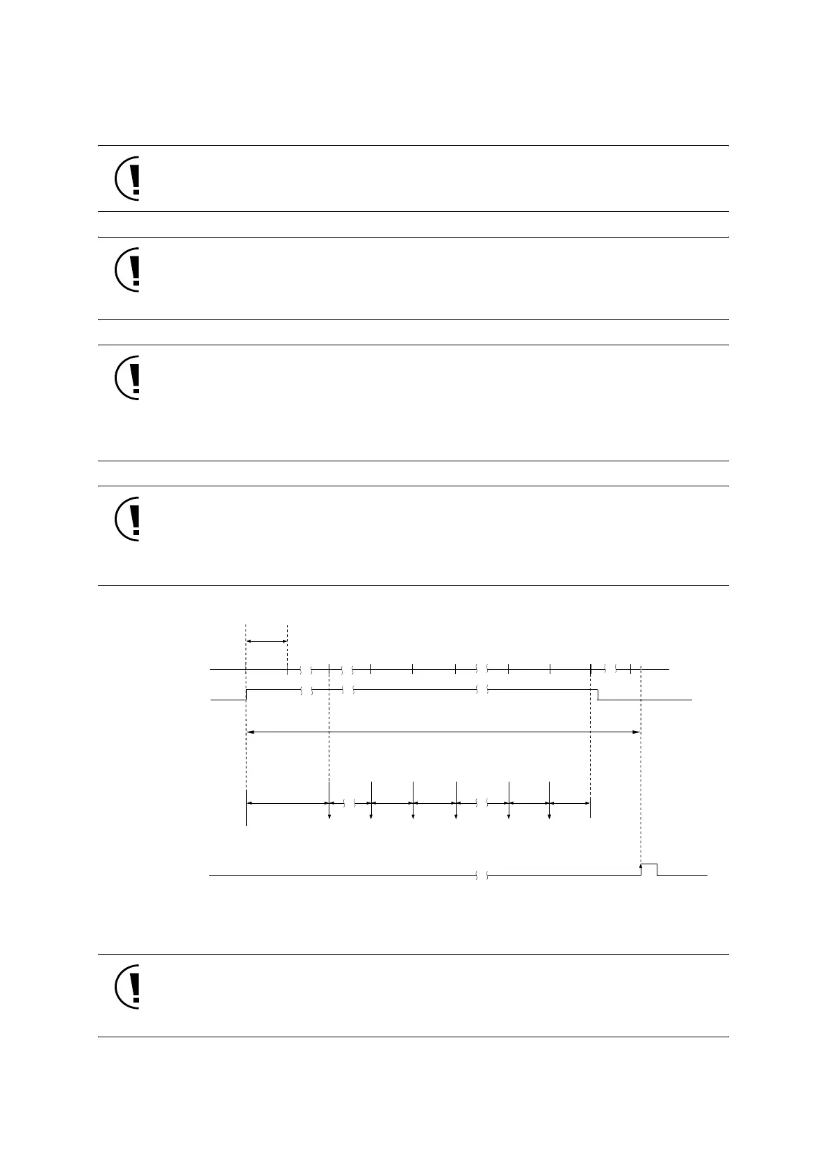
Figure:16.3.1 Operation of A/D conversion (sample hold time at T
ADCLK
× 2)
..
Before reading out the value of the A/D conversion, A/D conversion should be done several
times to prevent noise error by confirming the match of level by program, or by using the
average value.
..
2,3 4,5 61 17 18 19,20
ANST bit
A/D conversion clock
A/D conversion start
A/D conversion time
T
S
Sampling
bit 11
comparison
Determine
bit 1
Determine
bit 10
Determine
bit 11
A/D conversion
interrupt (ADIRQ)
Determine
bit 0
A/D conversion
end
converter
data store
TADCLK
7
bit 10
comparison
bit 0
comparison
preparation
period
 Loading...


