Parker EME
Specifications
192-120114 N5 C3I22T11 June 2008 401
Special encoder systems for
direct drives
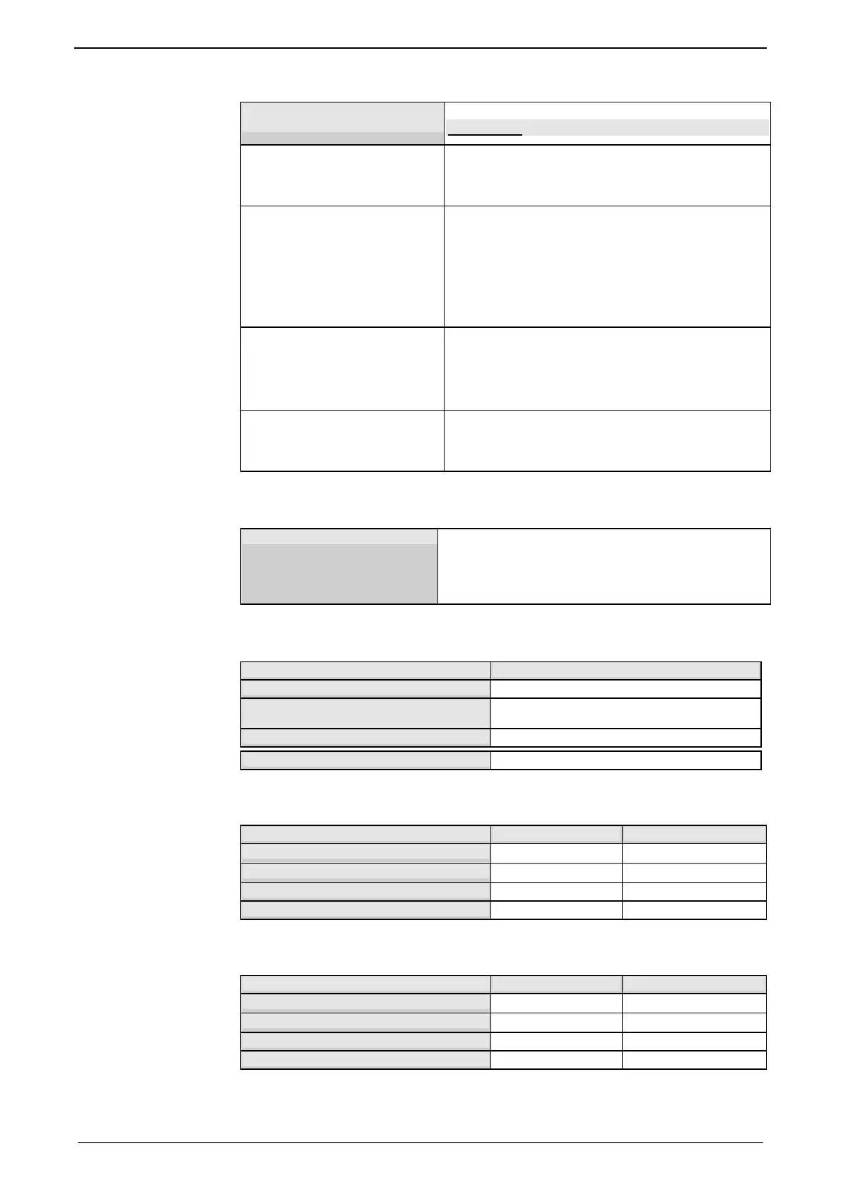
Option F12
Analog hall sensors
Sine - cosine signal (max. 5Vss; typical 1Vss)
90° offset
U-V Signal (max. 5Vss; typical 1Vss) 120° offset.
Encoder
(linear or rotatory)
Sine-cosine (max. 5Vss; typical 1Vss) (max.
400kHz) or
TTL (RS422) (max. 5MHz)
with the following modes of commutation:
automatic commutation (see page 347) or
Digital hall sensors (e.g. DiCoder
©
)
Digital, bidirectional interface
All EnDat 2.1 or EnDat 2.2 feedback systems
with incremental track (sine-cosine track)
linear or rotary
max. 400kHz Sine-Cosine
Distance coded feedback sy-
stems
Distance coding with 1VSS - Interface
Distance coding with RS422 - Interface (Enco-
der)
Feedback error compensation
Feedback error compensation
Automatic feedback error compensation (offset &
amplification) for analog hall sensors and sine-
cosine encoder can be activated in the MotorMa-
nager.
Motor holding brake output
Motor holding brake output Compax3
Voltage range
21 – 27VDC
Maximum output current (short circuit
proof)
1.6A
Minimum output current
150 mA
Securing of brake Compax3M
3.15A
Braking operation Compax3S0xxV2 1AC
Controller type S025V2 S063V2
Capacitance / storable energy
560μF / 15Ws 1120μF / 30Ws
Minimum braking- resistance
100Ω 56Ω
Recommended nominal power rating
20 ... 60W 60 ... 180W
Maximum continuous current
8A 15A
Braking operation Compax3S1xxV2 3AC
Controller type S100V2 S150V2
Capacitance / storable energy
780μF / 21Ws 1170μF / 31Ws
Minimum braking- resistance
22Ω 15Ω
Recommended nominal power rating
60 ... 450W 60 ... 600W
Maximum continuous current
20A 20A

 Loading...


