Setting up Compax3
C3I12T11
192-120113 N08 C3I12T11 - December 2010
Cascade control
In this chapter you can read about:
Structure of a cascade control ....................................................................................... 200
Cascade structure of Compax3...................................................................................... 200
In drive technology, a cascading structure with several controllers (normally 3) is
often used. This improves the control behavior. For this, additional sensors must be
fixed within the control path. You will get the structure of a cascade control.
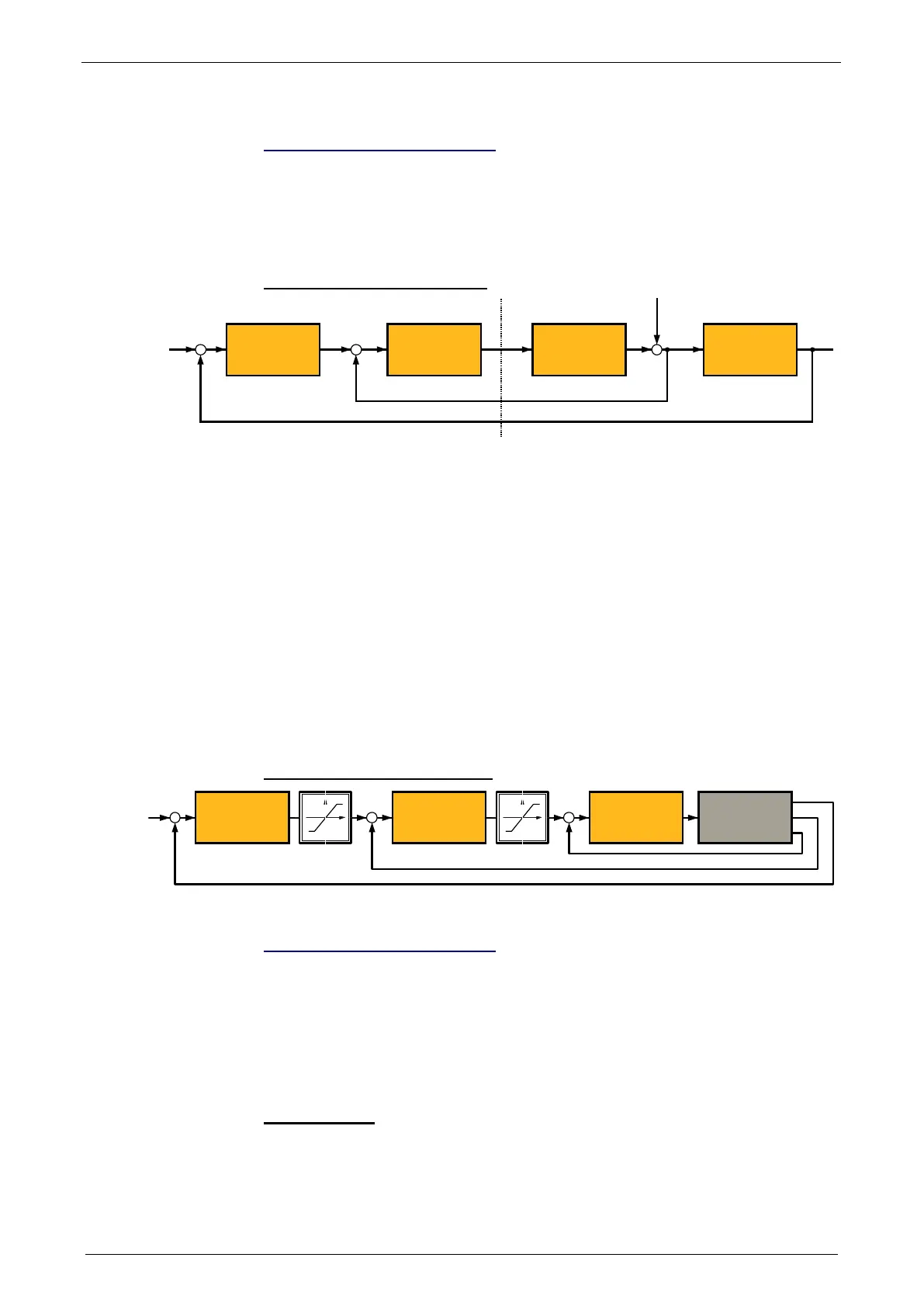
Structure of a cascade control
Z
Process / Prozess
X2X1W1W2
Controller1
Regler 1
Controller 2
Regler 2
Process Part 1
Streckenteil 1
Process Part 2
Steckenteil 2
W1 Setpoint value (setpoint) for the superposed controller 2
W2 Setpoint value (setpoint) for the subordinate controller 1
X2: Actual variable (actual value) for controller 2
X1: Actual variable (actual value) for controller 1
The cascade control offers the following advantages:
Disturbances occurring within the control path, can be compensated in the
subordinate control loop. Therefore they must not pass through the entire control
path and are thus compensated earlier.
The delay times within the path can be reduced for the superposed controller.
The limitation of the intermediate variables can be made by the control variable
limitation of the superposed controller rather easily .
The effects of the non-linearity for the superposed controllers can be reduced by
the subordinate control loops.
In the Compax3 servo drive, a triple cascade control is implemented with the
following controllers - position controller, velocity controller and current controller.
Cascade structure of Compax3
Current Controller
Stromregelung
Motor
Speed Controller
Drehzahlregelung
Position Controller
Positionsregler
Xw
X n i
Rigidity
In this chapter you can read about:
Static stiffness ............................................................................................................... 200
Dynamic stiffness .......................................................................................................... 201
Correlation between the terms introduced...................................................................... 202
The stiffness of a drive represents an important characteristic. The faster the
disturbance variable can be compensated in the velocity control path and the
smaller the oscillation caused, the higher the stiffness of the drive. With regard to
stiffness, we distinguish static and dynamic stiffness.
Static stiffness
The static stiffness of a direct drive is comparable with the spring rate D of a
mechanical spring, and indicates the excursion of the spring in the event of a
constant interference force. It is the ratio between the constant force FDmax of the
motor and a position difference. Due to the I term in the velocity controller, the
static stiffness is therefore infinitely high in theory, as the I term is integrated until