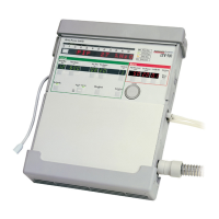
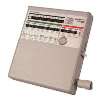
Page 1-6 LTV
®
Series ventilator Operator’s Manual
p/n 10664, Rev. Y
WARNING
Ventilator Service and Repair - All servicing or repair of the LTV
®
Series ventilator must be
performed only by a service technician certified by Pulmonetic Systems
Disabled Oxygen Inlet Pressure Alarms - When the oxygen blending option is not installed, the
Oxygen Inlet Pressure Alarms are disabled.
Patient Circuits – Pulmonetic Systems Patient Circuits, Exhalation Valve Assemblies and Water
Traps are shipped clean, not sterile.
Ultra Violet Light Sensitivity – The material used in the tubing of the “Re-usable” Patient Circuits is
not UV stable. Avoid exposure of the tubing to UV light.
PEEP Valve Rotation – Attempting to adjust the PEEP valve counterclockwise past zero (0) may
damage the PEEP valve assembly or cause circuit leaks.Accessories
Mounting Screws - Refer to the information contained in Pulmonetic Systems Replacement Screws
Kit, P/N 11149, to determine the appropriate accessories mounting screws or accessories
replacement screws location, type and length to use when removing or exchanging external
accessories on an LTV® Series ventilator.
Mounting Screw Use – Internal damage to the ventilator may result if the wrong length mounting
screws are used when installing or removing external accessories.
Specific Boot Replacement Screw Location - One leg of the upper protective boot has an
additional screw hole (furthest from the end of the leg); On earlier version ventilators (screw was
located in the upper hole in the leg of the boot) the use of a 3/16” mounting screw is required. On
current version ventilators (screw was located in the lower hole in the leg of the boot) the use of a 1/4”
mounting screw is required.
Specific Boot Installation Screw Location - One leg of the upper protective boot has an additional
screw hole (furthest from the end of the leg); On earlier version ventilators, the screw hole will align
with the upper hole in the boot and requires the use of the 1/4” mounting screw. On current version
ventilators, the screw hole will align with the lower hole in the boot and requires the use of the 3/8”
mounting screw.
Patient Circuit Accessories - The use of accessories such as Speaking Valves, Heat-Moisture
Exchangers and Filters create additional patient circuit resistance and in the event of a disconnection,
may impede the generation of a Low Pressure Alarm. Ensure that the Low Pressure Alarm settings
accommodate these types of accessories when used in combination with patient circuits.
Low Minute Volume Control Settings - The Low Minute Volume control should be set to its highest
clinically appropriate value. If there is a clinical need to set the Low Minute Volume alarm to lower
values or off (“- - -“), perform a clinical assessment to determine if an alternative monitor (i.e. a Pulse
Oxymeter with an audible alarm, or a Cardio Respiratory Monitor) should be used.