Page C-16 LTV
®
Series ventilator Operator’s Manual
p/n 10664, Rev. Y
Using the Remote Alarm Cable
Use the Remote Alarm Cable (P/N 10893) to connect the LTV
®
Series ventilator to third party, single
or dual tone remote alarm systems requiring a normally closed input signal terminated with a 51K
ohm series resistor. Devices connected to the Patient Assist port must be IEC 60601-1-1 certified.
• See Chapter 10 - Extended Features, Alarm Operations, for instructions on setting the Patient
Assist Port output signal for use with single or dual tone remote alarm systems.
Because the LTV
®
Series ventilator does not include an internal series resistor in the Patient Assist
output, a special cable has been designed which incorporates the resistor into the cable assembly
itself. The series resistor allows the remote alarm to detect and report both ventilator alarms and a
disconnected remote alarm cable.
Do not apply more than 120 Volts AC (VAC) to a remote alarm when it is connected to the ventilator.
CAUTION
Remote Alarm - Always verify that the remote alarm properly reports the LTV
®
Series ventilator
alarms before use.
Remote Alarm - Always follow the remote alarm manufacturer’s usage and maintenance
requirements to guarantee proper function of the device.
ATTENTION
Alarme à distance – Assurez-vous toujours que l’alarme à distance indique de façon adéquate les
alarmes du ventilateur LTV
®
avant d’utiliser le ventilateur.
Alarme à distance – Suivez toujours les exigences d’utilisation et d’entretien du fabricant de l’alarme
à distance afin d’assurer le fonctionnement adéquat de l’appareil.
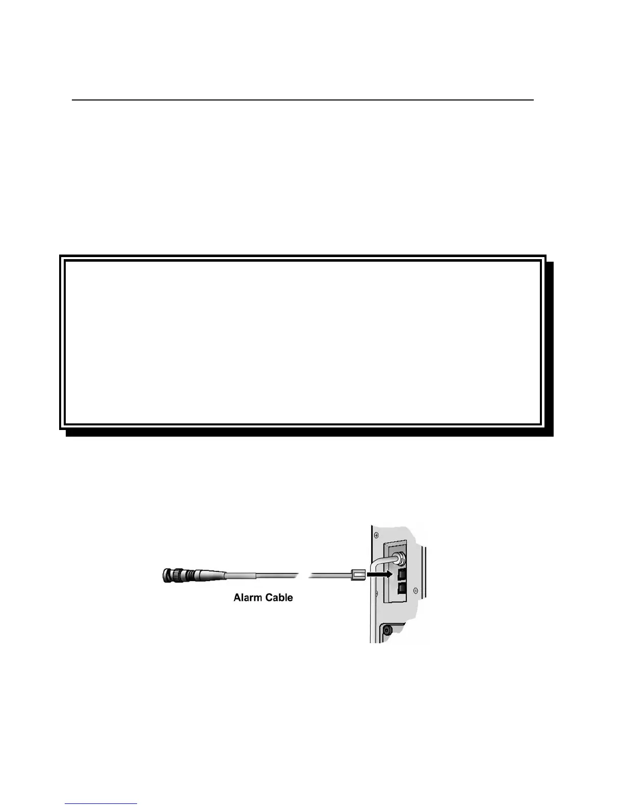
To connect the ventilator to the remote alarm:
1) Plug the cable’s modular jack into the Patient Assist port on the side of the LTV
®
Series ventilator.
2) If the remote alarm has a female BNC plug, connect the cable directly to the remote alarm's input
cable or connector and twist to secure.