4.6 Auto-Tuning
150 SIEPYEUOQ2A01G AC Drive Q2A Technical Manual
• Speed feedback detection-use F1-xx [F1: ENCODER] parameters (only with CLV)
Note:
Do Stationary Auto-Tuning if you cannot do Rotational Auto-Tuning. There can be large differences between the measured results and
the motor characteristics when Auto-Tuning is complete. Examine the parameters for the measured motor characteristics after you do
Stationary Auto-Tuning.
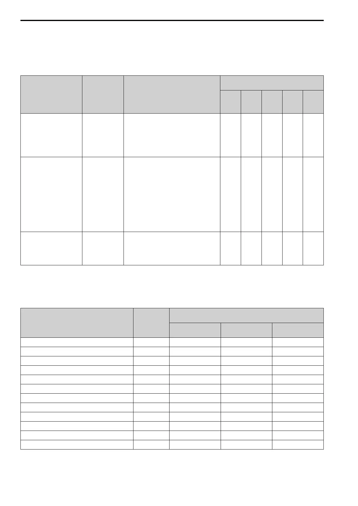
Table 4.7 Types of Auto-Tuning for Induction Motors
Type Parameter Settings Application Conditions and Benefits
Applicable Control Method
(Value of A1-02 [Control Method])
V/f
Control
(0)
PG V/f
Control
(1)
OLVec
tor
(2)
CLVec
tor
(3)
Adv
OLVec
tor
(4)
Rotary Auto Tune T1-01 = 0
• When you can decouple the motor and load the
motor can rotate freely while Auto-Tuning.
• When operating motors that have fixed output
characteristics.
• When it is necessary to use motors that have high-
precision control.
• When you cannot decouple the motor and load, but
the motor load is less than 30%.
× × × × ×
Static1 AutoTune T1-01 = 1
• When you cannot decouple the motor and load, but
the motor load is more than 30%.
• When the information from the motor test report or
motor nameplate is not available.
Note:
With Stationary Auto-Tuning, the energized drive
stays stopped for approximately 1 minute. During
this time, the drive automatically measures the
necessary motor parameters.
• When operating the motor with a light load after
Auto-Tuning.
The drive can automatically calculate the motor
parameter settings necessary for torque control. Set
T1-12 = 1 [Test Mode Selection = Yes] to do a test
run after Auto-Tuning.
- - × × ×
Static (R) T1-01 = 2
• After Auto-Tuning, the wiring distance between the
drive and motor changed by 50 m or more.
• When the wiring distance is 50 m or more in the V/f
Control mode.
• When the motor output and drive capacity are
different.
× × × × ×
■ Input Data for Induction Motor Auto-Tuning
To do Auto-Tuning, input data for the items in the following table that have an "×". Before starting Auto-Tuning,
record the information on the motor nameplate as a reference.
Table 4.8 Input Data for Induction Motor Auto-Tuning
Input Data Unit
Auto-Tuning Mode
(Value of T1-01 [Auto-tuning Mode Selection])
Rotary Auto Tune
(0)
Static1 AutoTune
(1)
Static (R)
(2)
T1-02 [Motor Rated Power] kW × × ×
T1-03 [Motor Rated Voltage] V × × -
T1-04 [Motor Rated Current] A × × ×
T1-05 [Motor Base Frequency] Hz × × -
T1-06 [Motor Poles Number] - × × -
T1-07 [Motor Base Speed] rpm × × -
T1-08 [PG PulsePerRevolution] - ×
*1
×
*1
-
T1-09 [Motor NoLoad Current] A - × -
T1-10 [Motor Rated Slip Frequency]
Hz - ×
*2
-
T1-11 [Motor Iron Loss]
W ×
*3
- -
T1-12 [Test Mode Selection]
*4
- - ×
*5
-
T1-13 [No-load Voltage]
V ×
*6
×
*6
-
*1 Input this value when A1-02 = 3 [Control Method = CLVector].
*2 0 Hz is displayed as the initial value. If you do not know the Motor Rated Slip Frequency, keep the setting at 0 Hz.
*3 Input this value when A1-02 = 0 or 1 [Control Method = V/f Control or PG V/f Control].