5.6 Safe Disable Input
228 SIEPYEUOQ2A01G AC Drive Q2A Technical Manual
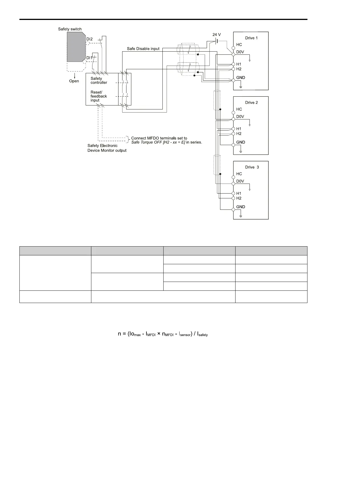
Figure 5.29 Connection Example to Use 24 V External Power Supply
Number of Possible Drives to Connect
Power Supply Digital Inputs 24 V Output Number of Drives
Internal power supply
(Drive 1)
Yes
(7-channel input)
Yes
*1
1
No 13
No
Yes
*1
4
No 17
External power supply -
Different for different external power
supply capacities
*2
*1 This is when you use a maximum of 150 mA.
*2 24 V, 12 mA is necessary for each drive.
Use this formula to calculate the number of units to connect:
• n: Number of units to connect
• Io
max
: Maximum current that the power supply can supply (234 mA for the internal power supply)
• I
MFDI
: Current consumed per MFDI (6 mA)
• n
MFDI
: Maximum number of MFDIs that can be activated at the same time (maximum of 7-channel)
• I
sensor
: Current externally supplied for sensor power supply (maximum of 150 mA)
• I
safety
: Current consumed by Safe Disable terminals H1 and H2 (12 mA)
Note:
Round the values to the first decimal place.
■ Enabling and Disabling the Drive Output (“Safe Torque Off”)
Example of drive operation when as the drive changes from the "Safe Torque Off" status to usual operation.