Parameter Details
12
12.7 H: TERMINALS
SIEPYEUOQ2A01G AC Drive Q2A Technical Manual 745
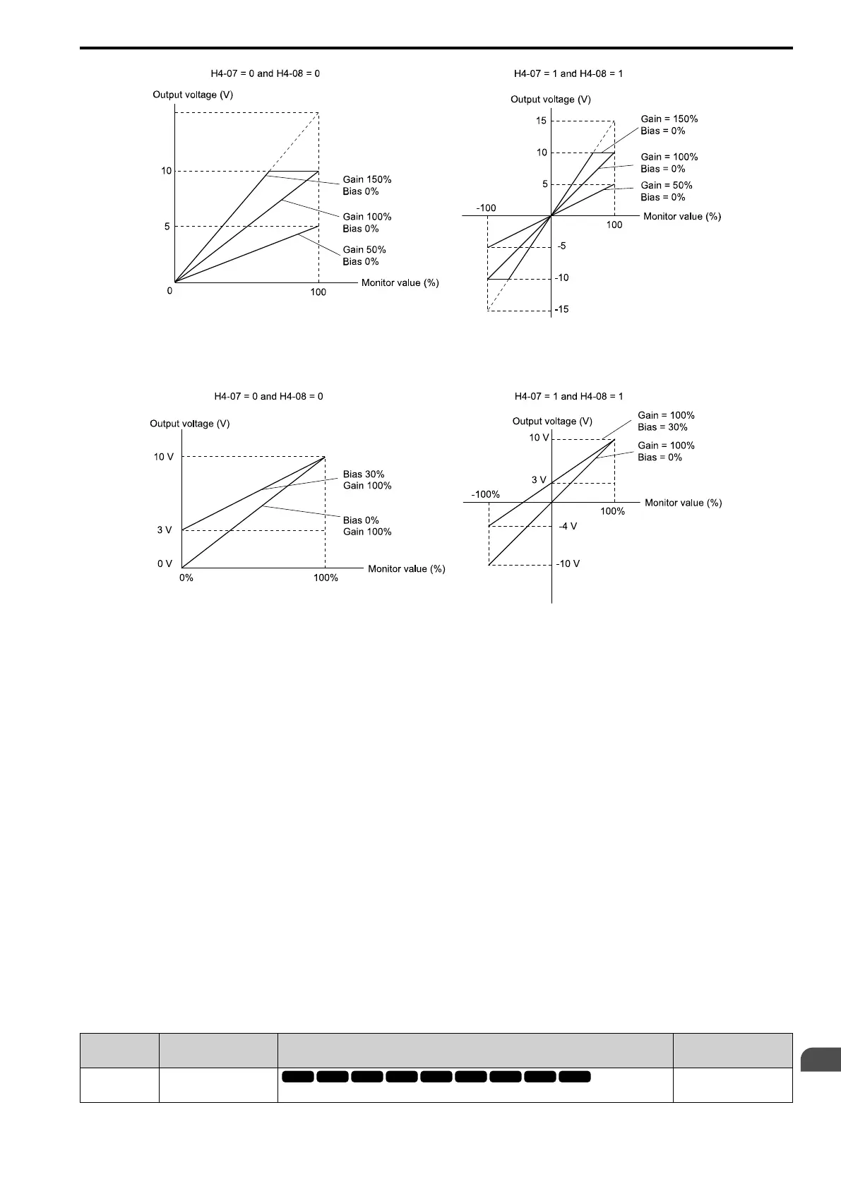
Figure 12.107 Analog Output Gain/Bias Configuration Example 1
For example, when the parameter value set to analog output is 0, and a 3 V signal is output to terminal AO1, H4-
03 [AO1 An.Out Bias] is set to 30%.
Figure 12.108 Analog Output Gain/Bias Configuration Example 2
Calibrate Terminal AO1
Stop the drive to calibrate meters. Use this procedure to calibrate:
1. Show H4-02 [AO1 An.Out Gain] on the keypad.
Terminal AO1 outputs the analog signal when the monitor item that you set in H4-01 [AO1 An.Out Select] is
100%.
2. Adjust H4-02 and monitor the meter scale connected to terminal AO1.
3. Show H4-03 [AO1 An.Out Bias] on the keypad.
The analog signal at the time when the monitor item selected with H4-01 is 0% is output from terminal AO1.
4. Adjust H4-03 while referencing the meter scale connected to terminal AO1.
Calibrate Terminal AO2
Stop the drive to calibrate meters. Use this procedure to calibrate:
1. Show H4-05 [AO2 An.Out Gain] on the keypad.
Terminal AO2 outputs the analog signal when the monitor item that you set in H4-04 [AO2 An.Out Select] is
100%.
2. Adjust H4-05 and monitor the meter scale connected to terminal AO2.
3. Show H4-06 [AO2 An.Out Bias] on the keypad.
Terminal AO2 outputs the analog signal when the monitor item that you set in H4-04 [AO2 An.Out Select] is
0%.
4. Adjust H4-03 and monitor the meter scale connected to terminal AO1.
■ H4-01 AO1 An.Out Select
No.
(Hex.)
Name Description
Default
(Range)
H4-01
(041D)
AO1 An.Out Select
Sets the monitor number to send from MFAO terminal AO1.
102
(000 - 999)
 Loading...