13.2.4 Communication Mapping Register Address Distribution
Frequency converter parameter registers
Frequency converter parameter registers correspond to the function codes one-
to-one. Reading and writing of related function codes can be achieved through
reading and writing of the contents in frequency converter parameter registers
via ModBus communication. The characteristics and scope of reading and writ-
ing function codes are in compliance with the frequency converter function code
description. The address of a frequency converter parameter register is com-
posed of a higher byte representing the function code group and a lower byte
representing the index in the group. The groups are mapped as follows:
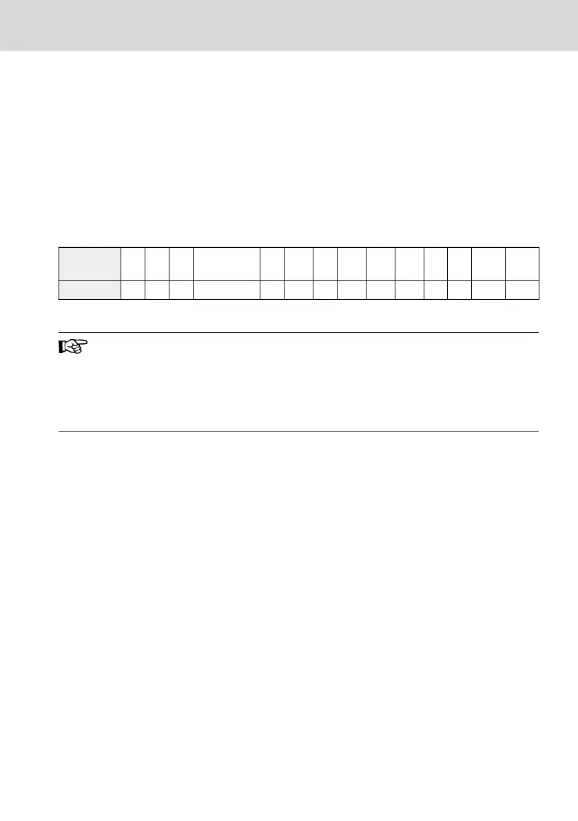
Address
high byte
0x00
0x01
0x02
0x03
0x04
0x05
0x06
0x07
0x08
0x09
0x0A
0x0B
0x0C
0x0D
Group b0 b1 S0 Reserved S2 S3 E0 E1 E2 E3 E4 H0
P0
(*)
d0
(**)
Tab. 13-23: Frequency converter parameter registers
(*)
: The manufacturer parameter group (Group P0) can always be
read (independent of the manufacturer password setting). It de-
pends on the password setting if the parameter can be modified
over communication.
(**)
: Parameters of the monitoring group (Group d0) are always
write-protected.
Examples:
To read out the module temperature (d0.16) of EFC 3600 frequency converter,
use register address 0x0D10 (0x0D = Group d0, index 0x10=16).
To set V/f curve mode (S0.00) of EFC 3600 frequency converter, use register ad-
dress 0x0200 (0x02 = Group S0, index 0).
Access to a non-existing function code will be acknowledged with exception
code 3 (see chapter 13.2.3 "ModBus Function and Message Format" on page
187).
EFC 3600
Bosch Rexroth AG
Communication Protocols
DOK-RCON03-EFC-3600***-IT03-EN-P
195/259