13.3.3 PROFIBUS Interface
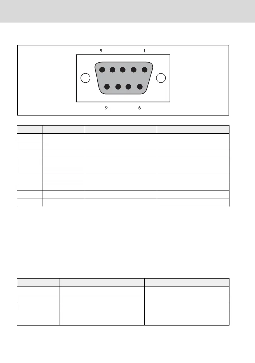
Fig. 13-4: PROFIBUS DB9 interface
Pin Terminal sign Terminal name Function description
1 NC – Reserved
2 NC – Reserved
3 PROFIBUS_B PROFIBUS terminal_B PROFIBUS data cable B
4 RTS Request for signal sending –
5 GND Power- –
6 Vcc Power+ –
7 NC – Reserved
8 PROFIBUS_A PROFIBUS terminal_A PROFIBUS data cable A
9 NC – Reserved
Tab. 13-27: Pin definition of PROFIBUS DB9 interface
13.3.4 Requirements for PROFIBUS Link
Cables used in PROFIBUS are shielded twisted pair cables. The shielding is able
to improve electromagnetic compatibility (EMC) ability. Unshielded twisted pair
cable may be used if there is less electromagnetic interference (EMI). Impe-
dance of the cable should be within 100 ~ 200 Ω. Cable capacity (among con-
ductors) should be < 60 pF/m, and conductor cross section should be ≥ 0.22
(24 AWG). Two kinds of cables are used for PROFIBUS with detail definitions
stated in table below.
Cable data
Type A Type B
Impedance 135 ~ 165 Ω (f = 3 ~ 20 MHz) 100 ~ 130 Ω (f > 100 kHz)
Capacity < 30 pF/m < 60 pF/m
Resistance ≤ 110 Ω/km ≤ 110 Ω/km
Conductor cross
section
≥ 0.34 (22 AWG) ≥ 0.22 (24 AWG)
Tab. 13-28: Type of PROFIBUS cable
Bosch Rexroth AG
Communication Protocols
EFC 3600
202/259
DOK-RCON03-EFC-3600***-IT03-EN-P