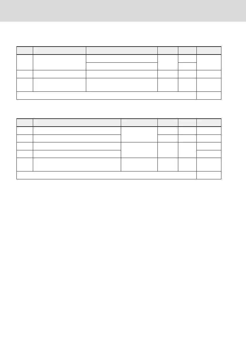
Frequency converter configuration
Code Name Setting range Min. unit Default Attri.
b0.20
Rated frequency convert-
er voltage setting
200 V: 200 ~ 240 V
1 V
220 V
STOP
400 V: 380 ~ 480 V 380 V
b0.21 Carrier frequency 1 ~ 15 kHz 1 kHz 4 kHz RUN/STOP
b0.22
Automatic adjustment of
carrier frequency
0: OFF; 1: ON 1 0 STOP
b0.23 ~ b0.29 Reserved
Monitoring display
Code Name Setting range Min. unit Default Attri.
b0.30 Running monitoring display
0 ~ 70
1 0 RUN/STOP
b0.31 Stop monitoring display 1 2 RUN/STOP
b0.32 User-defined proportion factor for velocity
0.01 ~ 100.00 0.01 1.00
RUN/STOP
b0.33 PID reference / feedback coefficient RUN/STOP
b0.34
Time constant for high resolution output
current
5 ~ 500 ms 1 ms 40 ms RUN/STOP
b0.35 ~ b0.39 Reserved
Setting range of b0.30 ~ b0.31:
0: Output frequency
1: Output rotation speed
2: Set frequency
3: Set rotation speed
4: Output voltage
5: Output current
6: Output power
7: DC bus voltage
8: Analog input voltage (AIV)
9: Analog input current (AIC)
10: User-defined set velocity
11: User-defined output velocity
12: Digital input status
13: Digital output status
14: PID target engineer value
15: PID feedback engineer value
16: Module temperature
Bosch Rexroth AG
Appendix
EFC 3600
222/259
DOK-RCON03-EFC-3600***-IT03-EN-P