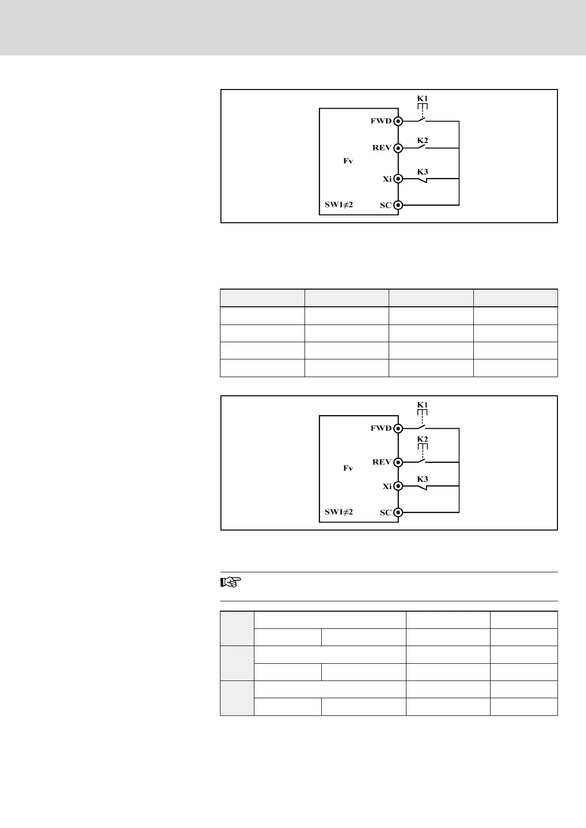
K1 is N.O. switch, which is activated with pulse edges
K3 is N.C. switch
K2 is for direction selection (Open: Forward; Closed: Reverse)
Fig. 7-29: 3-wire control mode 1
● 3: 3-wire control 2
K3 K1 K2 Running status
Open Edge / Inactive Edge / Inactive Stop
Closed Edge Inactive Forward
Closed Inactive Edge Reverse
Closed Edge Edge No change
Tab. 7-9: Logic of 3-wire control 2
K1 and K2 are both N.O. switch, which are activated with pulse edges
K3 is N.C. switch
Fig. 7-30: 3-wire control mode 2
If one of the digital inputs Xi (I = 1...8) is set to 7, “3-wire control”
is selected.
E0.01
Digital input X1 Factory default 0
Setting range 0...29 Minimum unit 1
E0.02
Digital input X2 Factory default 0
Setting range 0...29 Minimum unit 1
E0.03
Digital input X3 Factory default 0
Setting range 0...29 Minimum unit 1
DOK-RCON02-FV*********-IB08-EN-P Bosch Rexroth AG 129/259
Rexroth Frequency Converter Fv
Parameter Settings