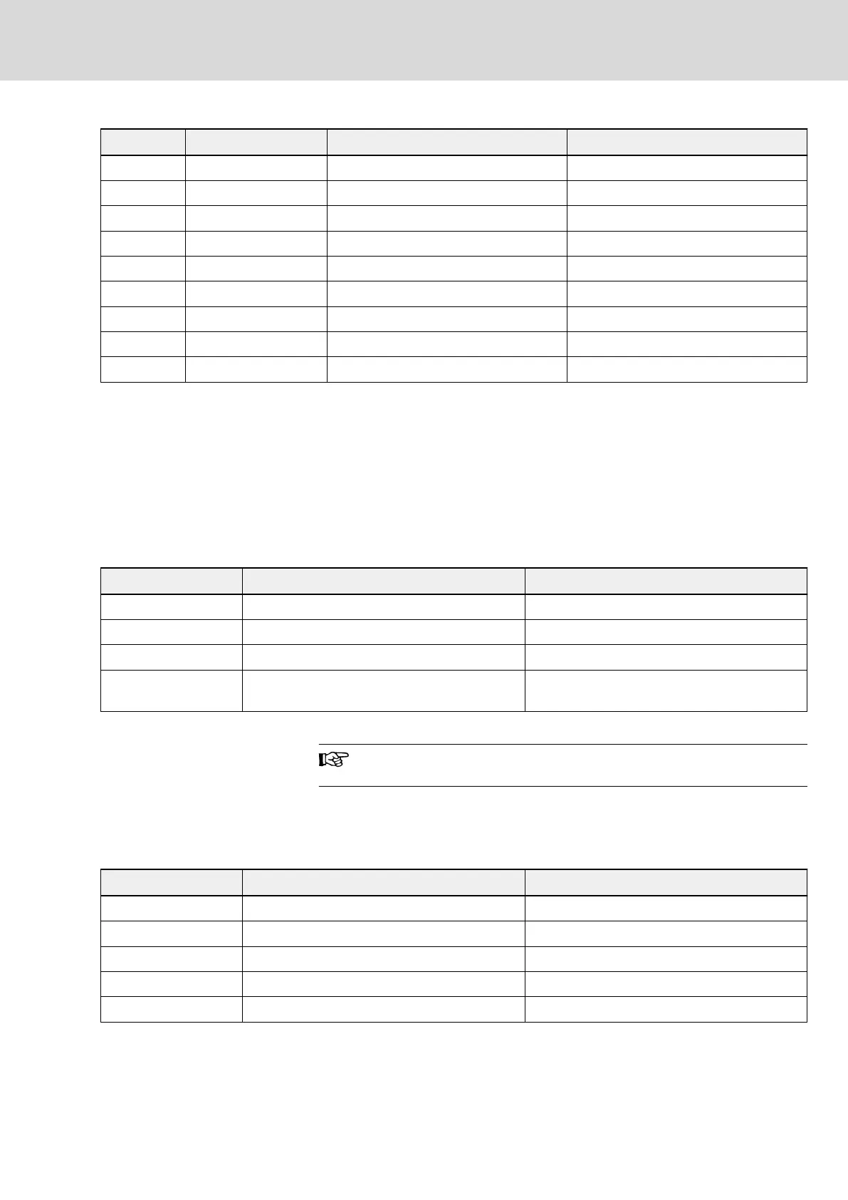
Pin No. Terminal sign Terminal name Function description
1 PE Terminal of bus cable shield Connects with bus cable shield
2 NC – Reserved
3 PROFIBUS_B PROFIBUS terminal_B PROFIBUS data cable B
4 RTS Request for signal sending –
5 GND Power- –
6 Vcc Power+ –
7 NC – Reserved
8 PROFIBUS_A PROFIBUS terminal_A PROFIBUS data cable A
9 NC – Reserved
Tab. 12-22: Definition of PROFIBUS DB9 Pins
Requirements for PROFIBUS link
Cable used is shielded twisted pair cable. The shield is able to improve elec‐
tromagnetic compatibility (EMC) ability. Unshielded twisted pair cable may be
used if there is less electromagnetic interference (EMI).
Impedance of the cable should be within 100...200 Ω. Cable capacity (among
conductors) should be < 60 pF/m, and conductor cross section should be ≥
0.22 (24 AWG). Two kinds of cables are used for PROFIBUS with detail defi‐
nitions stated in table below.
Cable parameters Type A Type B
Impedance 135...165 Ω (f = 3...20 MHz) 100...130 Ω (f > 100 kHz)
Capacity < 30 pF/m < 60 pF/m
Resistance ≤ 110 Ω/km ≤ 110 Ω/km
Conductor cross sec‐
tion
≥ 0.34 (22 AWG) ≥ 0.22 (24 AWG)
Tab. 12-23: Type of PROFIBUS-adapter cable
Standard Siemens PROFIBUS cable is (MLFB) 6XV1830-0EH10
(Type A), and connector is 6ES7972-0BA12-0XA0.
Relationship between communication rate and cables
Relationship between adapter’s communication rate and cable length is de‐
scribed in table below.
Baud rate Maximum length for each cable in [m] (Type A) Maximum length for each cable in [m] (Type B)
9.6...93.75 kbps 1000 1000
187.5 kbps 1000 600
500 kbps 400 200
1.5 Mbps 200 200
3...12 Mbps 100 100
Tab. 12-24: Relationship between communication rate and cable length
DOK-RCON02-FV*********-IB08-EN-P Bosch Rexroth AG 235/259
Rexroth Frequency Converter Fv
Communication Protocols