5.3 Wiring Terminals Description
5.3.1 Main Circuit Terminals
Main circuit terminals description
Terminal Description
L1, L2, L3 Mains supply input terminals
U, V, W Frequency converter output terminals
PB External brake resistor terminal
P1, (+) DC choke input or DC positive bus output terminal
(–) DC negative bus output terminal
Grounding terminal
Tab. 5-4: Main circuit terminals description
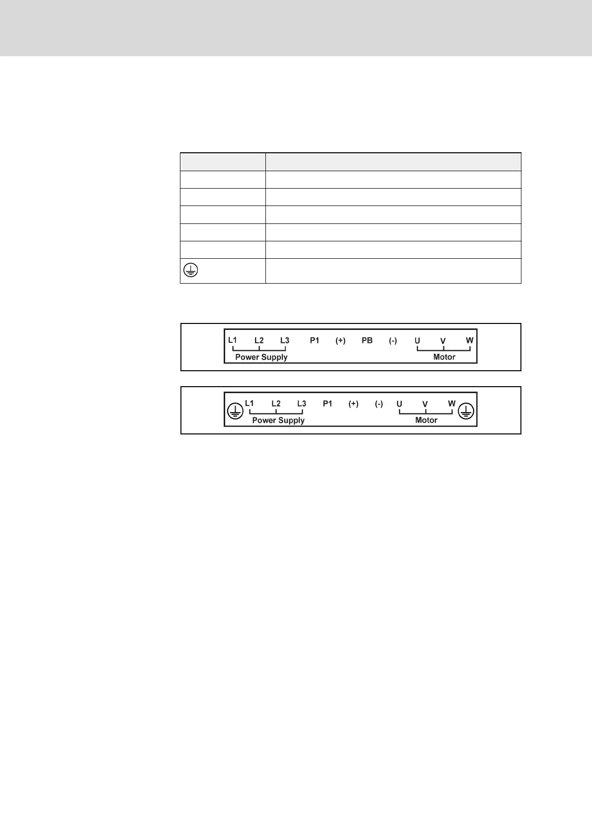
Main circuit terminals illustration
0K40...15K0
Fig. 5-12: Main circuit terminals illustration_0K40...15K0
18K5 and above
Fig. 5-13: Main circuit terminals illustration_18K5 and above
Bosch Rexroth AG DOK-RCON02-FV*********-IB08-EN-P54/259
Rexroth Frequency Converter Fv
Installation