10.3.3 Encoder Adapter Terminals
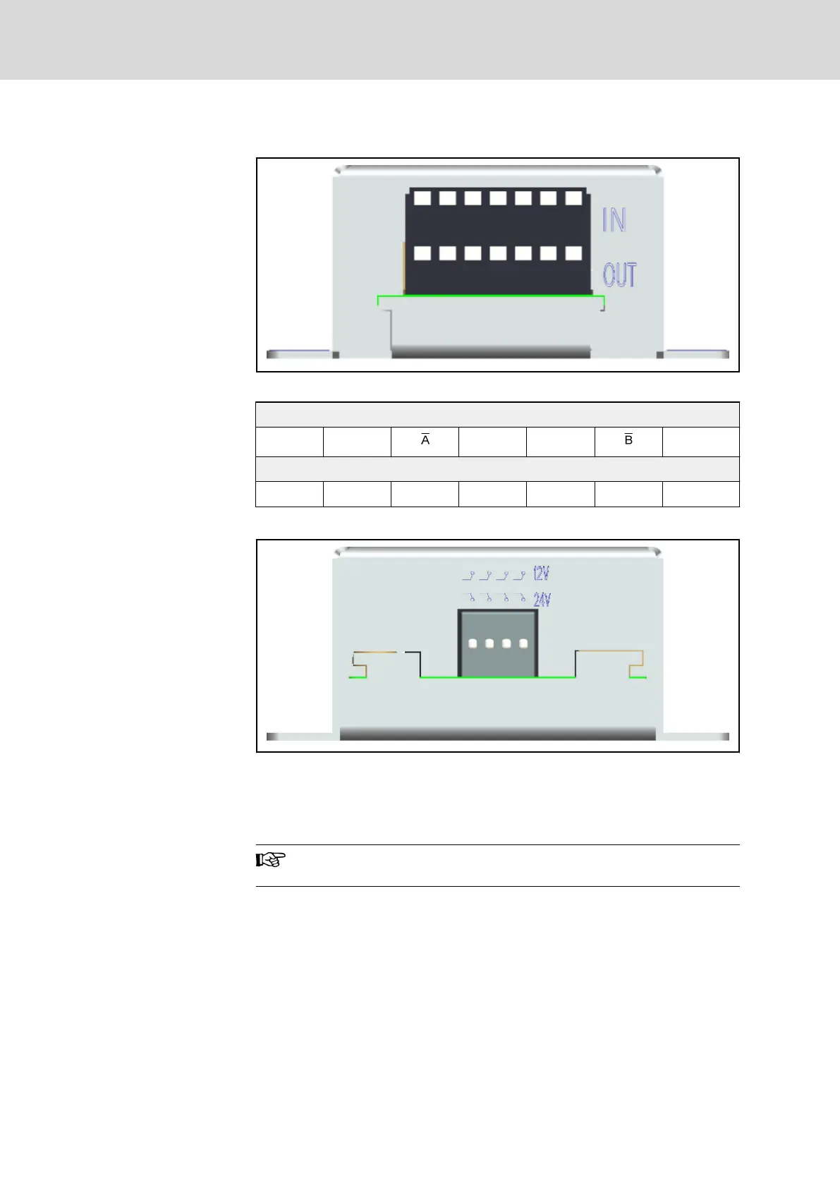
Fig. 10-19: Encoder adapter IN and OUT terminals
IN (Used to connect with motor encoder signals)
PGP2 A COM B PGP1
OUT (Used to connect with CPU board of the frequency converter)
PGP2 A+ A- COM B+ B- PGP1
Tab. 10-14: Encoder adapter IN and OUT terminals description
Switches down (by default) Supports 24 V power supply, corresponding to
PGP1-COM
Switches up Supports 12 V power supply, corresponding to
PGP2-COM
Fig. 10-20: Encoder adapter DIP terminals
For encoder wiring information, see chapter 5.3.5 "Encoder Sig‐
nal Selection" on page 60.
Bosch Rexroth AG DOK-RCON02-FV*********-IB08-EN-P210/259
Rexroth Frequency Converter Fv
Accessories

 Loading...


