7.4.3 Category E: Extended Parameters
Group E0: Analog and digital inputs
E0.00
2-wire / 3-wire control mode Factory default 0
Setting range 0...3 Minimum unit 1
● 0: Forward / Stop, Reverse / Stop
FWD REV Status
0 0 Stop
0 1 Reverse
1 0 Forward
1 1 Stop
Tab. 7-6: 2-wire control mode 1
● 1: Forward / Reverse, Run / Stop
FWD REV Status
0 0 Stop
0 1 Stop
1 0 Forward
1 1 Reverse
Tab. 7-7: 2-wire control mode 2
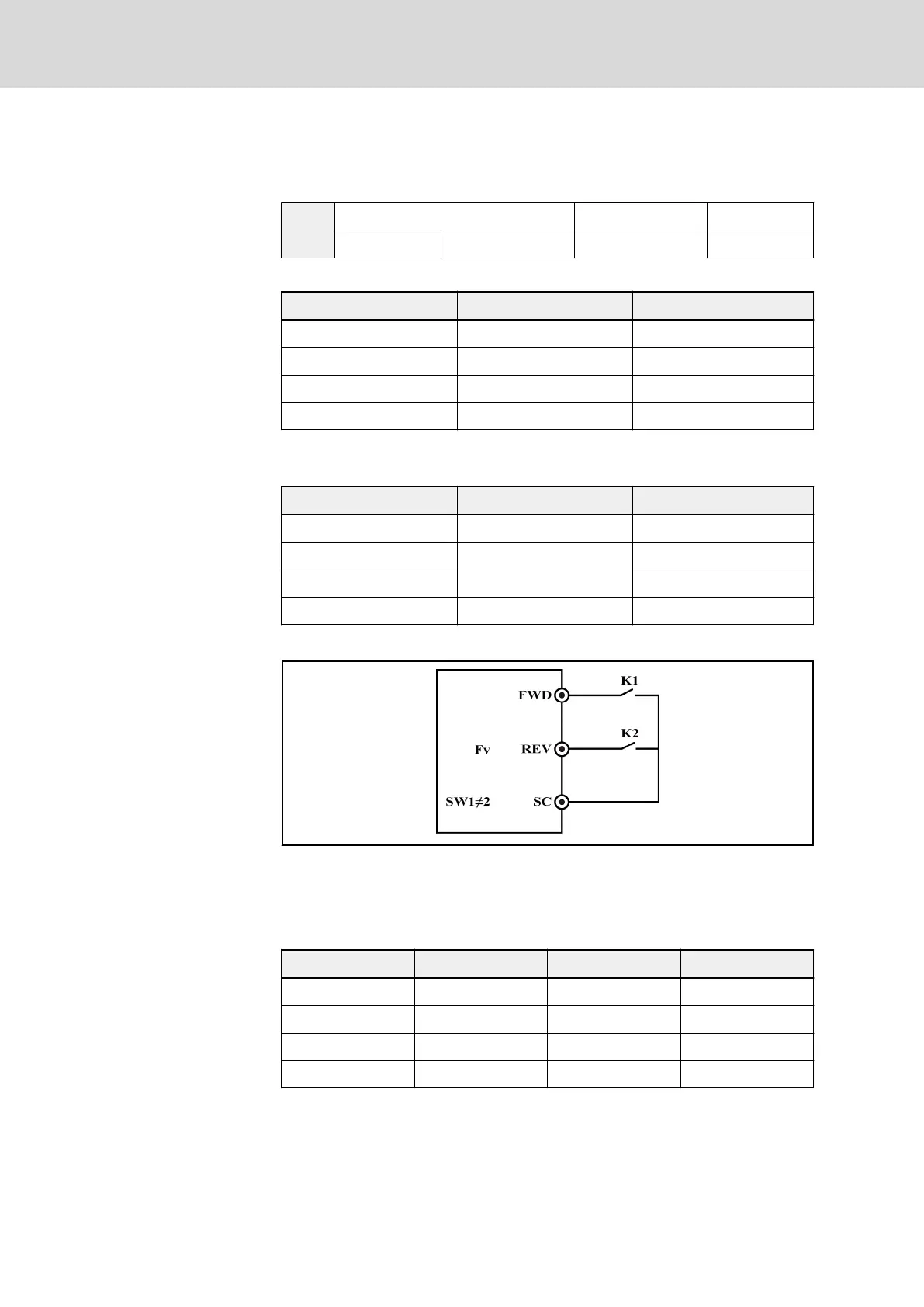
K1 is N.O. switch, which is activated with pulse edges
K2 is for direction selection (0: forward; 1: reverse)
SW1 jumper position cannot be set as 1-2, 3-4
Fig. 7-28: 2-wire control mode
● 2: 3-wire control 1
K3 K1 K2 Running status
Open Edge / Inactive Closed / Open Stop
Closed Edge Open Forward
Closed Edge Closed Reverse
Closed Inactive Closed / Open Stop
Tab. 7-8: Logic of 3-wire control 1
Bosch Rexroth AG DOK-RCON02-FV*********-IB08-EN-P128/259
Rexroth Frequency Converter Fv
Parameter Settings