EMC measures
● Conductor of bus cable (signal cable) must be twisted, and shielded and
installed separately with electrical power cable with a distance of at least
20 cm. Bus cable shielding layer should be grounded at one end. Termi‐
nal PE at terminal block X2 is taken as connecting terminal of the shield‐
ing layer. The terminal PE is only valid at the 1
st
pin of DB9 socket or
when DB9 metal cover is connected with the shielding layer of bus ca‐
ble.
● Conductors of communication connection cable (signal cable) for adapt‐
er and frequency converter must be twisted, and shielded and installed
separately at a reasonable distance. Shielding layer for communication
cable should be grounded at one end.
● Signal cable and electric power cable should be orthogonal in case of
crossing.
● Signal cable should be as short as possible.
● Large area is required for the connection of shielding layer.
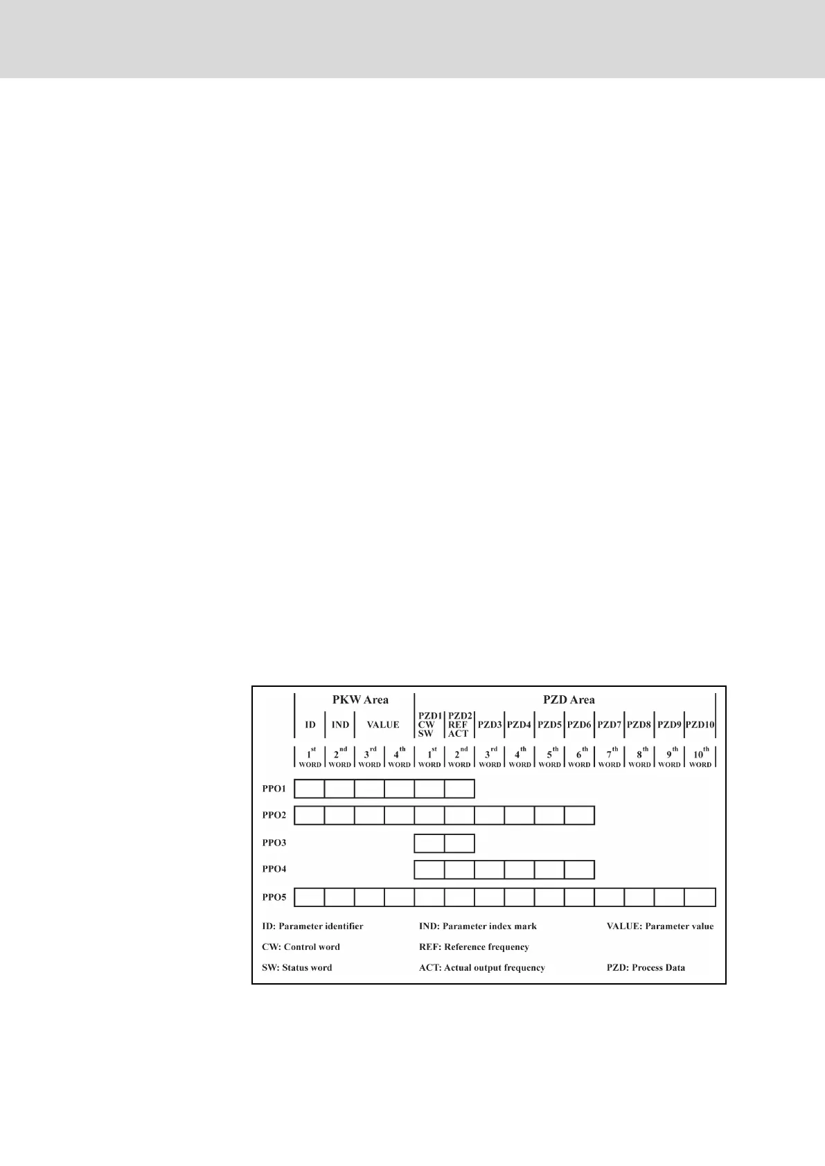
12.3.4 Periodical Data Communication
PPO data type
PROFIBUS-DP defines data structure for periodical data communication as
PPO (the Parameter Process date Object). Rexroth PROFIBUS adapter sup‐
ports 5 PPO types shown in figure below. PPO message is divided into two
data areas in terms of transmission data contents:
Parameter area (PKW area): read or overwrite the parameter of a certain
function code of slave.
Process data area (PZD area): including control word and reference frequen‐
cy (data flow from master to slave), or status word, actual output frequency
and other status monitoring values of slave (data flow from slave to master).
For detail descriptions of PKW area and PZD area, please refer to chapter
"PKW parameter area" on page 237 and chapter "PZD process data area"
on page 241.
Fig. 12-6: PPO type
Bosch Rexroth AG DOK-RCON02-FV*********-IB08-EN-P236/259
Rexroth Frequency Converter Fv
Communication Protocols