5.3.5 Encoder Signal Selection
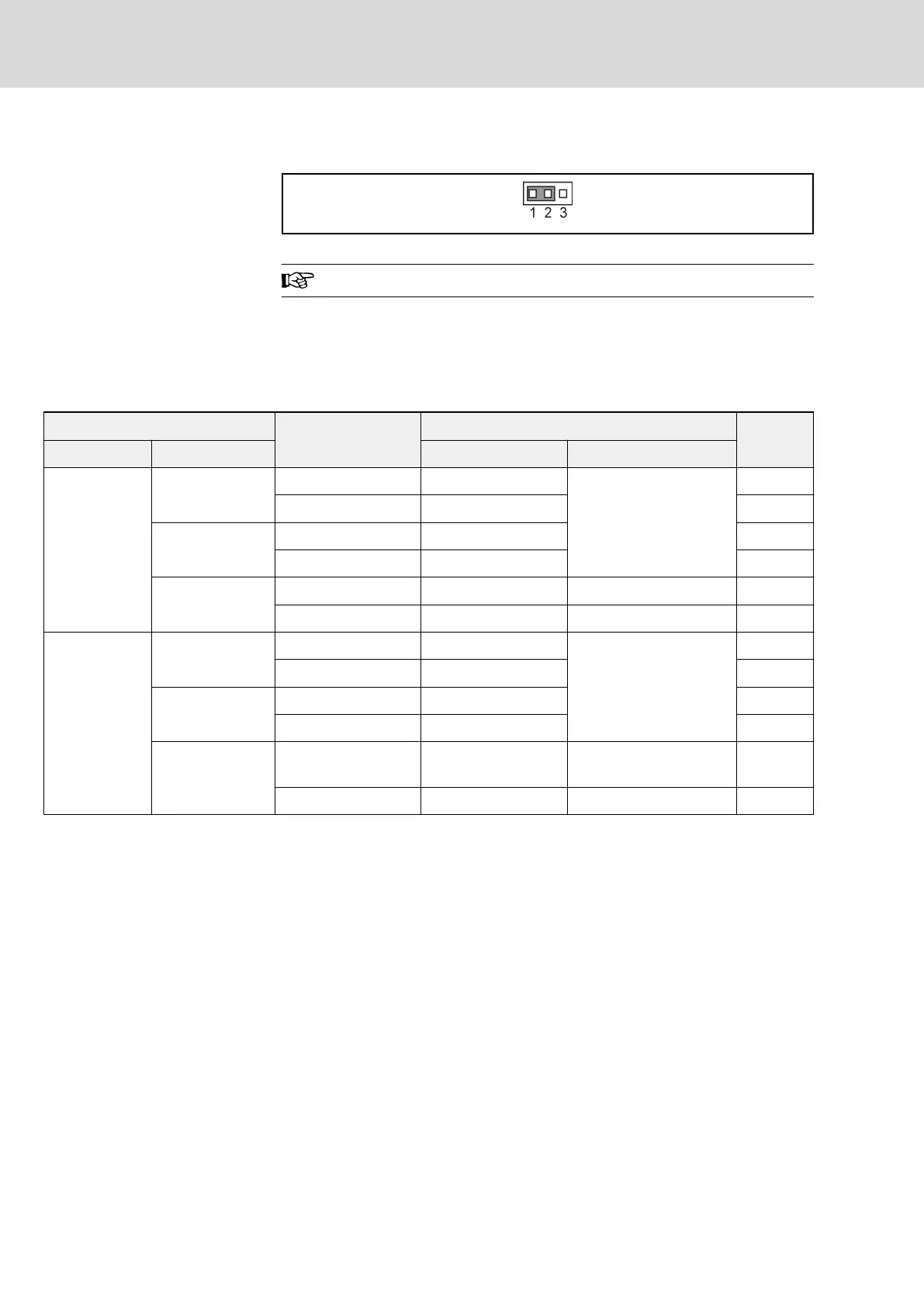
Fig. 5-21: Encoder jumper JP5
The factory default position of jumper JP5 is at 1-2.
Encoder input signals are set by jumper JP5:
Position 1-2: 5 V encoder power supply is provided by PGP2.
Position 2-3: 12 V encoder power supply is provided by PGP2.
The wiring of the encoder is described in the table below:
Encoder power supply
Encoder signal
Fv terminal wiring
Reference
Supply option Voltage Encoder signal wire Other connection
Internal
PGP1 (+24V)
A, B A-, B-
Connect encoder adapter
between Fv terminals
and encoder signals
Wiring 1
A+, A-, B+, B- A+, A-, B+, B- Wiring 2
PGP2 (+12V)
A, B A-, B- Wiring 3
A+, A-, B+, B- A+, A-, B+, B- Wiring 4
PGP2 (+5V)
A, B A-, B- Connect A+, B+ to PGP2 Wiring 5
A+, A-, B+, B- A+, A-, B+, B- − Wiring 6
External
+24V
A, B A-, B-
Connect encoder adapter
between Fv terminals
and encoder signals
Wiring 7
A+, A-, B+, B- A+, A-, B+, B- Wiring 8
+12V
A, B A-, B- Wiring 9
A+, A-, B+, B- A+, A-, B+, B- Wiring 10
+5V
A, B A-, B-
Connect A+, B+ to exter‐
nal supply
Wiring 11
A+, A-, B+, B- A+, A-, B+, B- − Wiring 12
Tab. 5-6: Encoder wiring description
Bosch Rexroth AG DOK-RCON02-FV*********-IB08-EN-P60/259
Rexroth Frequency Converter Fv
Installation

 Loading...


