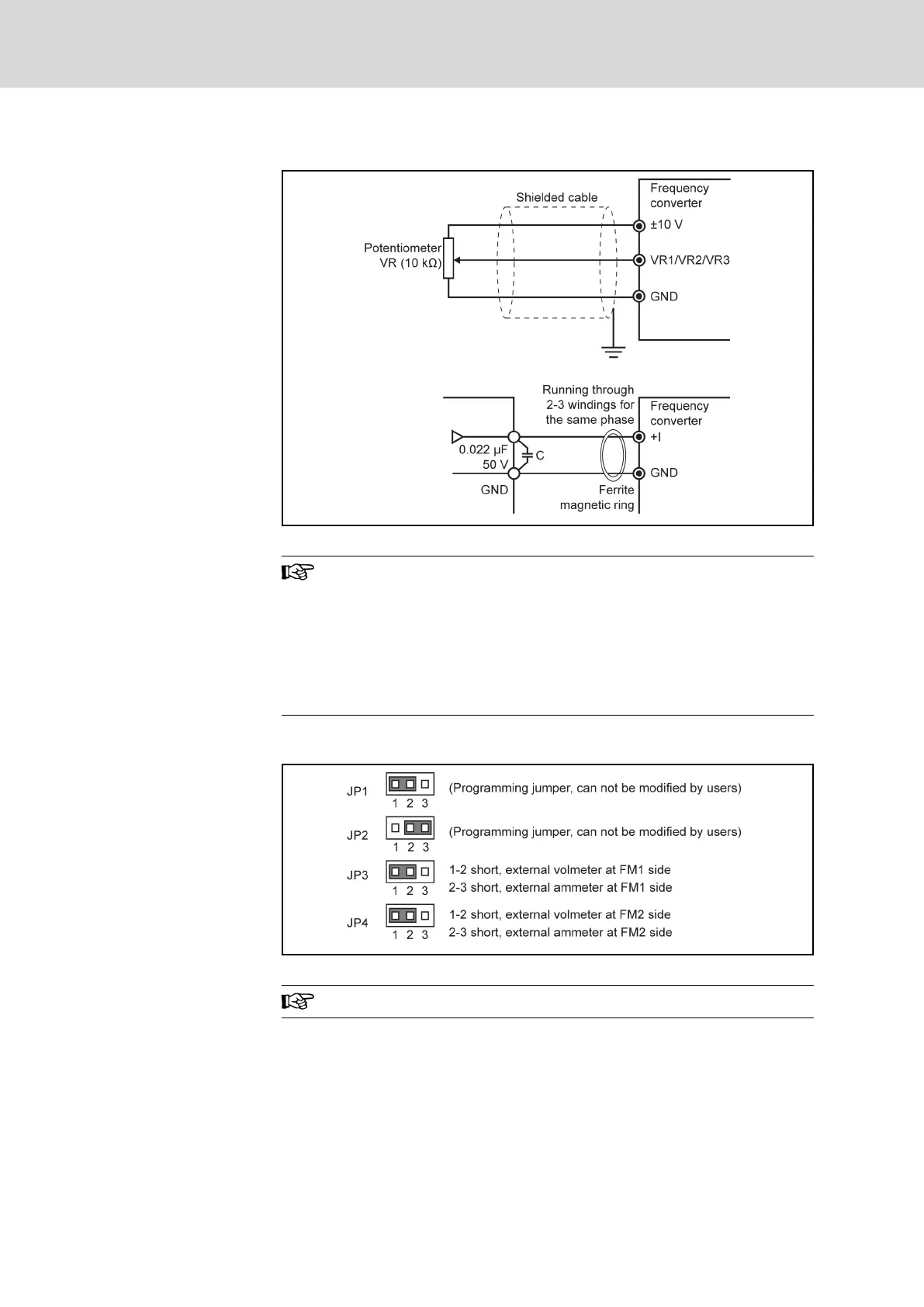
Analog input terminals (±10 V, VR1, VR2, VR3, GND, +I)
Fig. 5-17: Analog input terminals (±10 V, VR1, VR2, VR3, GND, +I)
1. For connection of low level analog signals, which are easily
affected by external interference, the wiring length should be
as short as possible (less than 20 m), shielded cables must
be used.
2. Incorrect operation may occur due to interference on the an‐
alog signal. In such cases, connect a capacitor and ferrite
core at the side of output of the analog signal, as shown
above.
5.3.3 Jumper Wiring
Fig. 5-18: Jumper description
Shown above are factory defaults.
Bosch Rexroth AG DOK-RCON02-FV*********-IB08-EN-P58/259
Rexroth Frequency Converter Fv
Installation